Helping design and engineering professionals discover, evaluate and specify technologies and processes that shorten the design cycle and enable success.

May 2026 Special Focus: Artificial Intelligence in Design and Simulation
In this Special Focus Issue, learn about the latest developments in the integration of artificial intelligence into engineering workflows.

Design & Simulation Software Guide 2025
In this Special Issue, Digital Engineering presents its second annual guide to design and simulation software vendors.
Nothing quite caps off a miserable day at work than pulling into your drivewaytrailing with you a chorus of heavily squealing brakes. Since this loud, monotonoussound generated by brake systems is unanimously perceived negatively and verydifficult to overcome, brake squeal represents a persistent quality issue forautomotive OEMs and brake system suppliers.
General Motors, together with LMS, developed a new process that effectively combinesadvanced testing with systematically correlated static and dynamic simulationsto identify and help fix brake squeal early in the design process. GM, one ofthe world's largest vehicle manufacturers, validated this method by characterizinga 13kHz intermittent squeal, and has since used it on several current developmentprograms.
The ability to measure and model brake squeal dynamics is a dramatic step forwardin our noise and vibration reduction efforts. This has generated substantial savingsin engineering cost and development lead-time.
Figure 1: An LMS Virtual.LAB analysis of the finite component models of individualbrake system components developed in CATIA.
 The Challenge of Modeling Brake Squeal
Brake squeal, generated by brake systems under operation, is an extremely complexphenomenon that's difficult to model. The characteristics of the different brakesystem components, the way these parts are put together, the grease that is usedto lubricate parts and connections, the temperature at the brake pads, and thefriction between brake pads and rotors all affect the tendency of the brake tosqueal. The resonances of the individual components interact heavily with eachother, making the phenomenon even more difficult to control. Brake squeal hastraditionally been addressed with an iterative design-build-test process becauseregular FE (finite element) analyses are not accurate enough. With this time-consumingapproach, problems are extremely expensive to fix since they are usually not identifieduntil relatively late in the design process.
The three of us successfully developed a systematic and rigorous correlationand updating process to reproduce and predict high-frequency brake squeal dynamics.Our process begins with the creation of an initial FE model of the complete brakecorner. This model helps us determine an optimal set of measurement locationson the brake corner assembly. Experimental modal analyses performed on the mainindividual components of the brake system are used to update their respectiveFE component models by
means of manual tuning and automatic
optimization routines(see Figure 1, above). Then, a similar sequence of modal testing and model updatingis executed on the entire brake assembly (see Figure 2, below right).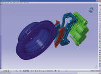
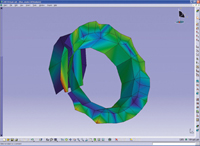
As a final step, an Operating Deflection Shape (ODS) of the brake assembly ismeasured while the brake is squealing. This ODS is compared to the stability resultsfrom a complex eigenvalue FE analysis. Once these results match, we can be virtuallycertain that the unstable modes gained from the analysis depict the same squealmechanisms as those on the ODS (see Figure 3, below right). 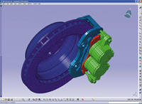
Figure 2: This LMS Virtual.LAB screen shot shows the finite element model ofthe assembled brake system modeled in CATIA.
Validating the Methodology
We used a brake corner exhibiting a 13 kHz squeal to validate this new predictionmethodology. In this particular case, a short squeal occurred once or twice perrevolution of the brake rotor.
The first step consisted of creating the FE model, selecting measurement locations,and generating the test geometry using LMS Gateway. The modes of the originalFE model were used to determine whether the mesh was sufficiently detailed tosupport accurate modal simulations. They also helped us determine the appropriatenumber of degrees of freedom for the test geometry and their spatial distribution.Additionally, the software generated Modal Assurance Criteria (MAC), a measureof resemblance or colinearity, for each pair of modes.
The goal of selecting the correct measurement points is to minimize the valueof the off-diagonal MAC terms in the resulting matrix. Achieving this assuresthat the data acquired from the selected measurement points will actually providecomplete and accurate modal results. For each cheek of the brake rotor, we selectedtwo concentric circles with 36 measurement points. Other measurement points werelocated on the brake pads, caliper, brackets, and axle.
Figure 3: The simulated Operational Deflection Shape (ODS) of a squealing brakesystem as executed by LMS Virtual.LAB.
Dynamic ODS
For convenience reasons, we performed the ODS next, instead of at the end ofthe process. The Running Modes module of LMS CADA-X was used to execute the ODSassessments. A brake noise dynamometer enabled the engineers to manually replicatethe operating conditions required to produce the squeal. A laser Doppler vibrometer(LDV) captured the out-of-plane rotor deflections, while small lightweight accelerometerstracked in-plane rotor deflections and deflections on nonrotating components.The axle and associated fixture were attached to a large stationary mass, andbrake pressure was applied at three different levels, corresponding to the pressurerange under which squeal occurred.
The conditions of the system, particularly the rotational wheel speed and brakepressure, were kept constant throughout the tests. Measuring all points on thecomplete brake assembly required different measurement runs with one common referencechannel, corresponding to one point on the caliper.
We split the analysis into three parts: the outboard and inboard cheeks of thedisk (both out-of-plane) and the in-plane measurements. This split was neededbecause the front and rear cheeks could not be measured simultaneously by theLDV. A 48-channel LMS data acquisition system, including LMS CADA-X T-MON andS-MON postprocessing, a microphone trigger, accelerometers, and the LDV, wereused to acquire the data for the ODS.
We saved the measured data as cross-powers of the responses with respect to thereference signal and auto-power of the reference signal. The amplitude-correctedcross-powers were animated to create the ODS. While acquiring in-plane data, thedata acquisition setup was also needed to track the position of the disk withrespect to the timing of squeal events. This enabled accurate positioning of themeasurements in space.
Static Modal Analyses
The same locations used for the ODS measurements were also used for the individualexperimental component assessments. LMS CADA-X Modal Analysis handled this seriesof assessments. Modifying the geometry and material properties of an individualcomponent model made it possible to tune the model so as to have it nicely correlatedwith the measured modal responses.
Once all component models were validated and updated, we analyzed the modal characteristicsof the entire assembly, using similar operating and boundary conditions that generatedthe squeal during the ODS measurements. The correlation of the complete assemblywas performed starting with the lower frequencies where the interactions of thecomponents with each other tended to dominate. We tuned the stiffness of all theconnections using the LinkSolver routine in LMS Gateway. Again, complex eigenvalueanalysis was performed to identify the unstable modes, which were subsequentlycompared to the previously measured ODS.
The FE model of the considered brake corner showed three unstable modes witha nearly identical shape and all within 150Hz of the frequency range of the experimentalODS. Both the test and the analysis shapes were similar, exhibiting a relativewalking motion between the two rotor cheeks.
Brake Squeal Fixed
These results demonstrate that, with proper validation, analysis can serve asa predictive and diagnostic tool to help address brake squeal problems as highas 15kHz relatively early in the design process. The key to the success of theprocess is the systematic and rigorous correlation between physical tests andvirtual FE modeling, at both the component and system level, and under staticand dynamic conditions. Once we thoroughly verified the analytical model, we canuse their information to identify and fix brake squeal problems much earlier inthe design cycle. After validating this method, we have moved it into GM's mainstreamdevelopment process and used it on several actual programs.
Tinghui Steven Shi is an engineer at GM's Pontiac, Michigan, Truck Center; Mark Riefe works as an engineer at GM's Milford, Michigan, Proving Ground; and Steven Dom is an engineer for LMS International, Engineering Services. Send us your feedbackon this article through e-mail c/o [email protected].

DE's editors contribute news and new product announcements to Digital Engineering. Press releases may be sent to them via [email protected].
Follow DEJoin over 90,000 engineering professionals who get fresh engineering news as soon as it is published.


About Us · Contact Us · Editorial Team · Advertising · Privacy Policy · Subscriber Services · © 2026 Digital Engineering 24/7 · Peerless Media