Helping design and engineering professionals discover, evaluate and specify technologies and processes that shorten the design cycle and enable success.

May 2026 Special Focus: Artificial Intelligence in Design and Simulation
In this Special Focus Issue, learn about the latest developments in the integration of artificial intelligence into engineering workflows.

April 2026 Special Focus Issue: Generative Design
In this Special Focus Issue, Digital Engineering takes a look at how generative design solutions can be used across different types of design problems and with a variety of manufacturing approaches to accelerate design space exploration, and…
The days of CAM operators having to work with dumb 3D solid models by printingout 2D flat drawings to obtain tolerances and dimensions are finally coming toan end. Such information is generally called nonnominal or GDandT (geometricdata and tolerances). Although nonnominal data hasn't yet been associated withthe solid models in a machine-readable manner—except for MCAD-to-CAM communicationsin integrated products from the large MCAD/CAM developers—some tools enablingsuch association now exist and are being tested. And some MCAD companies havemade it much easier for CAM programs to access the data, even if not yet in anautomated manner.
 The Industry Is Starting to Wake Up
 Most CAM programs create toolpaths for many different kinds of machining—prismaticand complex parts, for which exact tolerances are essential, and mold and dieapplications, where surface smoothness tends to be of greatest interest. For thepast few years, John Callen, vice president of technical marketing for Gibbs andAssociates, has been the most outspoken proponent of MCAD companies making nonnominaldata available in a computer-readable form. And he now sees bright light at theend of the tunnel. "The ]MCAD] industry is starting to wake up to the value ofnonnominal data associated directly with the solid model," Callen says.
For example, the three major MCAD/CAM developers—UGS, Dassault Systemes, andPTC—all have the capability internally. They, and most other MCAD developers,are currently studying and testing the newly introduced ISO standard, STEP AP203 Second Edition, as well as a similar standard from the ASME, Y1441, both ofwhich contain GDandT data associated with the solid model. SolidWorks providesAPI (application programming interface) tools to access nonnominal data, and Autodeskis working on encoding nonnominal data in its drafting subsystem, according toCallen.
"UGS wants to make the full model data available to third parties," Callen says,"and they provide so many ways to do so that it can get confusing." One way isvia the Parasolid modeling kernel, "But the nonnominal data itself exists outsideof Parasolid," he explains.
Another way to get nonnominal data is via the production and manufacturing (PMI)format of JT. However, this is still only a visualization file with the data annotated.Vynce Paradise, a director for NX Machining at UGS, says that a team is workingon making the nonnominal data computer-available via
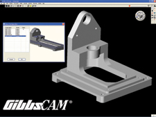
Below, left: GibbsCAM's ability to read native SolidWorks part and assembly filesincludes being able to access various configurations in the file.
 Callen says that other MCAD companies are also working on this, but are undernondisclosure agreements. From the viewpoint of GibbsCAM, he says, "We supportindustry standard formats, license the commercial kernels, and use a reverse engineeringsolution to work with native CATIA files. Customers want us to be able to dealwith whatever native ]MCAD] files they use, and ]MCAD] vendor facilitation ofthis objective is undergoing transition." Specifically, he says, the Parasolidand ACIS modeling kernels can be licensed to act as lightweight data servers makingdata associated with the solid model available.
MCAD interoperability issues tie into the CAM connectivity initiatives. Asa Trainer,PTC's director of Product Management focusing on interoperability, says that anumber of CAD groups are currently testing the shifting of syntax from STEP AP203 to AP 203 Second Edition, which incorporates nonnominal content, althoughthe tests are not specific to nonnominal data. "Overall, there's a shift awayfrom boundary representation as a transfer tool," Trainer says. "Everyone is lookingat CHAPS ]construction history and parametric shapes] and GDandT, which is intwo STEP formats—AP 203 Second Edition and AP 214. The latter is being drivenprincipally in Germany by the Pro-STEP community there. AP 203 Second Editionharmonizes with AP 214's capabilities, but is more flexible and has additionalcontent."
Trainer believes that, in time, it will be possible for vendors to get a usefulmechanism for transferring enriched information around the CAD model for CAM dimensions,quantities, and tolerances. He cautions, however, that while this informationcould be interpreted directly by machine, it will be hard for the vendor to validate."Vendors are hoping that a set of recommended practices will let content and presentationof content be embedded in the solid model."
What industry needs most, he believes, is agreement that everyone needs uniformaccess to tolerances and ways to join up areas of knowledge. "People shouldn'tbe talking about being design engineers or manufacturing engineers. Rather, theyshould become design and manufacturing engineers, as much as possible in a worldwhere design and manufacturing are often done by different companies."
Some things don't transfer well between MCAD and CAM, no matter how hard peopletry. Paradise of UGS says, "We're putting effort into translation of surface finishtolerances, but so far, we've found no useful, effective way to do this."
Get More Information —DE Editors |

DE's editors contribute news and new product announcements to Digital Engineering. Press releases may be sent to them via [email protected].
Follow DEJoin over 90,000 engineering professionals who get fresh engineering news as soon as it is published.


About Us · Contact Us · Editorial Team · Advertising · Privacy Policy · Subscriber Services · © 2026 Digital Engineering 24/7 · Peerless Media