Helping design and engineering professionals discover, evaluate and specify technologies and processes that shorten the design cycle and enable success.

May 2026 Special Focus: Artificial Intelligence in Design and Simulation
In this Special Focus Issue, learn about the latest developments in the integration of artificial intelligence into engineering workflows.

Design & Simulation Software Guide 2025
In this Special Issue, Digital Engineering presents its second annual guide to design and simulation software vendors.
The need for analyzing an entire assembly or at least the essentialparts of a subassembly early in the design process is becomingincreasingly important. When validating assembly form and fit,real-world behavior under structural loads can be quite different fromjust the geometry and dimensional tolerances considered by MCADprograms. Therefore, contact analysis is a major factor when joining ormating components with fasteners, such as rivets and bolts. Other thanexperimenting with an expensive and time-consuming physical prototype,finite element analysis (FEA) is the only reliable method fordiscovering whether such a mechanism will work.Adaptive Methodology
3G.author uses a proprietary adaptive FEA technology based on the h-pmethod. This adaptive FEA methodology automatically controls simulationaccuracy and speeds linear and nonlinear contact analysis.
The adaptive FEA technology uses selective and simultaneous escalationof the polynomial order of FEA approximation and local mesh refinementto reach convergence of an approximated finite-element solution to aprecise mathematical solution of the problem. This methodology combinesthe strength of both the p-method and h-method, where the p-method hashigh overall convergence rates and the h-method is excellent for localstress picks and concentrations.
|
|
|
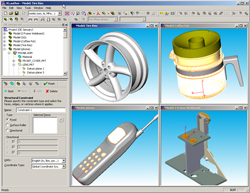
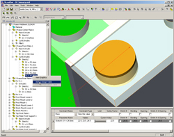
| Figure 1: This view of the3G.author environment shows MCAD models loaded from different programsand a Function Study Wizard window. | Figure 2: This illustration of a frame weldment model illustrates 3G.author'sContactWizard and its array of capabilities. |
The assessments of numerical algorithm accuracy are presented to theuser in a manner that's simple to learn and understand. 3G.author'sadaptive technology is applied to virtually every type of analysis itsupports. The process is straightforward and easy-to-use for mainstreamusers. Without advanced FEA training reliable simulation results can beachieved even for complex assembly validation cases.
3D Solid and Shell Meshing
Thedefault meshing functionality is fully automated and transparent to theuser, so the mainstream user employs a virtually "meshless" process.3G.author begins by reading in a MCAD model and finishes withgeometry-related validation results in the postprocessing stage. Themeshing algorithm automatically detects necessary mesh sizes based onthe geometrical and other pertinent information.
3G.author is fully associative with popular 3D MCAD systems, includingAutodesk Inventor, PTC's Pro/Engineer and Wildfire, Solid Edge, andSolidWorks. Data from CATIA can be read, as can standard geometry fileformats, such as STEP, IGES, Parasolid, and SAT. With fullassociativity, 3G.author provides access and graphical navigation tothe entire feature-based and dimension-driven presentation of the MCADassembly. This makes it possible to drive important dimensions withinthe package for validating a family of assemblies or quickly estimatinga design performance envelope by running what-if studies.
Contact Analysis
Geometriesfrom different MCAD sources can be read by 3G.author (see Figure 1).Bi-directional associativity with models is simultaneously maintainedeven from different MCAD sources in the same design validation projectauthor. To facilitate collaboration, the MCAD program does not have tobe installed on the same desktop as 3G.author, providing additionalleverage for optimizing MCAD and CAE licensing.When multipleconfigurations are created for validating a family of assemblies,performing what-if and trade studies, or running design optimizations,only the corresponding clone of the model is changed in the 3G.authordatabase. However, a new assembly created in the database can be savedto the original MCAD database from the 3G.author interface.To speed the learningprocess, a Function Study Wizard can be used tostart the validation of an assembly author. When the type of analysisis defined, the Wizard guides the user through steps to input materialproperties, loading conditions, and assembly structural restraints.Material properties are read from the MCAD program, manually input oredited, or extracted from a user-built material library or fromWeb-based databases like matweb.com (Internet browsing functionality isembedded). After input, the Wizard begins the simulation. Meshing,contact detection, FEA problem formulation, and solution are automatic.When the result is available, the Wizard switches to the postprocessingmode. Advanced users can set up problems and solve them without theWizard.
When contact detection is automated, changing the geometry-basedtolerance can control the process. A manual detection option isavailable for more advanced users of 3G.author (see Figure 2, above).
Modeling Real-World Cases
Mainstreamdesign engineers can model real-world assemblies with static anddynamic (harmonic, time-dependent, and random) loading. They can alsorun trade and what-if studies as well as design of experiments. Accessto feature-based, dimension-driven MCAD assembly models allows anembedded spreadsheet to drive dimensions for what-if studies tovalidate a family of assemblies, or run on-the-fly optimizationscenarios with different goals and criteria. 3G.author'sproblem-solving capabilities cover special cases, such as sheet metal,and general cases, such as thin-wall type assemblies. The defaultassembly that 3G.author can model is a bolted/welded assembly, which ismodeled without any additional user interaction. More complex casesinclude modeling sliding conditions (in which contact geometricentities can slide against each other) and separation conditions withor without sliding (in which the program checks body-to-bodyno-penetration conditions).
|
| |
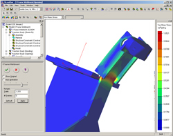
| Figure 3: Here, the frame weldment undergoes a Von Mises stress analysis withnonlinearcontact conditions. | Figure 4: The frame weldment is being used here to illustrate the result ofan assemblythermal analysis. |
Shrink-fit conditions can be modeled by creating geometricaloverlapping parts in an assembly and releasing it by simulatingstructural static equilibrium equations. The designer creates initialsizing of parts, which are geometrically overlapping in the MCAD file.3G.author finds the deformable shape of the assembly and correspondingstresses, while overlapping is released due to the deformations.
In an upcoming release, elastic spring conditions can be modeled.Currently, contact is modeled as elastic spring with user definedstiffness.
Figures 3 and 4 (above) show the results of structural and thermalassembly design validation, where modeling of contact with separation,shrink-fit, and bonded conditions have been used for assemblysimulation.
Conclusion
Forupfront design analysis 3G.author has capabilities for modelingreal-life cases, including different linear and nonlinear contactconditions; and static and dynamic (harmonic, time dependent, orrandom) loading conditions. Analysis of the entire assembly provides aquick assessment of design performance, as well as validation andoptimization of the design without the expense of physical prototypes.
Editor'snote: This article was derived from a white paper prepared by Dr. YuriKizimovich. View the full-length version.
Dr. Yuri Kizimovich is the CTO at PlassoTech, Inc. Send feedback about this article through e-mailc/o [email protected].
Product Information
3G.author
PlassoTech, Inc.
plassotech.com

DE's editors contribute news and new product announcements to Digital Engineering. Press releases may be sent to them via [email protected].
Follow DEJoin over 90,000 engineering professionals who get fresh engineering news as soon as it is published.


About Us · Contact Us · Editorial Team · Advertising · Privacy Policy · Subscriber Services · © 2026 Digital Engineering 24/7 · Peerless Media