Helping design and engineering professionals discover, evaluate and specify technologies and processes that shorten the design cycle and enable success.


April 2026 Special Focus Issue: Generative Design
In this Special Focus Issue, Digital Engineering takes a look at how generative design solutions can be used across different types of design problems and with a variety of manufacturing approaches to accelerate design space exploration, and…

Electrum utilizes the 3DEXPERIENCE platform on the cloud to develop their new electric motorcycle
Electrum, a new brand of electric motorcycles, utilizes the 3DEXPERIENCE platform. Their mission is to support Indonesia’s shift to low-carbon, sustainable transport and to ultimately help the country’s government achieve its vision of net…
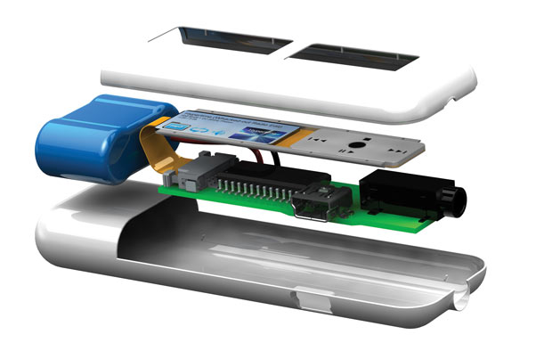 Even consumer electronics as simple as MP3 players can contain both rigid and flexible printed circuits, requiring tight cooperation between the MCAD and ECAD design teams. Image courtesy of Siemens PLM Software.
Gotta get all the air out! It’s a mandate that Craig Armenti and his colleagues at Zuken have heard time and time again. In the era of smaller, lighter connected devices, wasted space is the greatest design sin. Conversely, the ability to pack all the necessary electromechanical components in the smallest possible space is a feature of optimal design. Therefore, in the way a device’s housing unit and its internal circuits fit together, the room for error is much smaller -- quite literally.
“Look at your mobile phone or the thermostat on your wall,” says Armenti, applications engineer at Zuken. “More and more components are going into it. Your thermostat probably has Wi-Fi now.”
In the past, the MCAD-ECAD collaboration headache was a simple communication problem: To come up with a neutral file format that lets each discipline transmit its respective design to the other. But to design a connected device, where the outer shell and the internal parts must fit like hand and glove, the two sides must work together closer than ever before.
A format like IDF (intermediate data format), which is supported by most industry-standard software from both sides, removes the communication barrier between MCAD and ECAD disciplines, but many experts feel a new lingua franca is needed.
“The industry has matured in many ways, but the formats we’ve been using to exchange information with ECAD haven’t really kept up. In the past couple of years, we’ve had some good interaction with MCAD and ECAD vendors to develop a standard called EDMD,” says Ashley Eckhoff, senior product manager for NX at Siemens PLM Software.
EDMD (electrical design mechanical design) is a protocol championed by ProSTEP iViP, an international association that develops and defines standards for product data management and virtual product creation. “It’s actively maintained, so we meet with other CAD and ECAD vendors monthly or bimonthly to develop it to include what the modern designers need,” says Eckhoff.
“The technologies and design methodologies are changing very quickly, but IDF/IDX (incremental data eXchange) hasn’t really morphed fast enough. We’ll continue to support them, but we also work with ECAD companies to directly support custom standards,” notes Lou Feinstein, senior portfolio manager at SOLIDWORKS.
SOLIDWORKS also plans to support the emerging EDMD format. “I actually sit on the board for EDMD at ProSTEP iViP,” says Feinstein.
The connected devices of the IoT (Internet of Things) era are more than functional equipment. They’re usually marketed as wearable gadgets that also double as fashion accessories (for example, smartwatches and wireless headsets). Because they’re usually in close contact with the user’s skin, the heat generated by the internal circuits is a critical consideration.
John Wilson, electronics product specialist at Mentor Graphics’ mechanical analysis division focuses on thermal and airflow analysis of PCBs (printed circuit boards). His software arsenal includes FloTHERM, FloEFD and FloTHERM XT -- CFD (computational fluid dynamics) packages from Mentor Graphics.
“The thermal design for a consumer product is not like a piece of hardware sitting in a server room. You certainly don’t want the users wearing it to burn themselves. You don’t even want them to think it’s getting warm, because that’s generally perceived as a defect or a flaw. They may call the manufacturer for replacement or to return it,” observes Wilson.
The usual solution to eliminate hotspots, Wilson says, is to isolate the heat-generating component or to distribute the heat across a larger area. “In these devices, the mechanical shape is critical to the thermal performance of the device. Nobody cares about the shape of the chassis of something sitting inside a server room, but the shape matters in consumer goods, and small tolerances make a huge difference in them. It’s even more important for the electronics designer to work closely with his or her mechanical counterpart,” he says.
Presenting the analysis results to clients and management teams, who are often nontechnical, also requires some tact, Wilson learned. When conducting software-driven analysis, engineers tend to remove minor details (like rounded edges and holes) that don’t make a difference in the simulation. But that could make the analytical model look significantly different from the original product design in the screenshots and animation clips showing the simulation results.
“I learned that, even if certain design elements are irrelevant to the product’s thermal performance, I should retain their geometry because they [the clients] are more likely to trust what I’m proposing if they recognize the product from its shape,” says Wilson.
In the mechanical CAD industry, ANSYS is better known for its simulation and analysis products, but among electrical CAD designers, the company is known for ANSYS Icepak, a CFD package to simulate heat transfer and fluid flow inside integrated circuit (IC) packages. Icepak is based on an ANSYS Fluent solver. It’s one of the products used by electronics and electrical engineers to develop cooling strategies. Such products are expected to become a critical part of the design workflow in the era of IoT.
Outsiders might not be aware of it, but in the PCB industry, flexible boards -- PCBs designed with bendable plastic substrates -- have emerged as an alternative to the traditional rigid boards. Their appeal comes from the ability to fit into tight corners and conform to oddly shaped products. Insiders refer to them as “origami boards.”
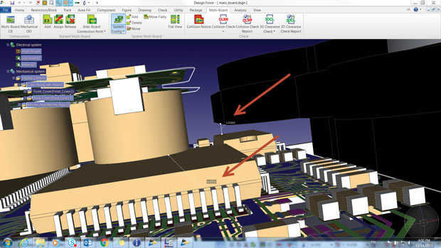 Zuken’s CR-8000 Design Force supports displaying all three boards of a camera design along with the enclosure in an editable format. Image courtesy of Zuken.
“Camera companies have become the masters of PCB origami,” says SOLIDWORKS’ Feinstein. “The cameras have become really small, and a lot of circuits have to fit inside them. Even in cellphones, there are multiple circuit boards that are folded. So what you see is electrical design that’s mechanical in nature. That adds new complexity.”
The need for these flexible boards is not only seen in hardware design -- it’s prompting new software capabilities. “Flexible boards are so common that they prompted a significant investment to our ECAD module in the PTC Creo 3 Release to support them,” says Brian Thompson, senior vice president of CAD, PTC.
Siemens PLM Software’s Eckhoff points out: “They introduce new problems, like bend regions. The board flexes with certain operations, like opening and closing of a phone, so you can’t place soldered components on the bend region.”
“Consumer goods are usually defined by the enclosure, or the shape -- not the board,” says Zuken’s Armenti. “So if there’s going to be more than one board, usually [engineers] want to use a mix of rigid and flexible boards.” Clearance for a rigid board is fairly straightforward, but figuring out the space constraint and thermal impact of a flexible board is much more complicated, especially when the bended board is expected to heat up the nearby mechanical features.
Previously, PCB designers could work efficiently in 2D space, in schematics representing the board layout, but the flexible boards demand a 3D workspace, with the option to visualize the boards both in flattened and folded states (as you would with sheet metal design). With its software CR-8000 already in 3D, ECAD developer Zuken is well positioned to tackle the flexible boards.
“As the designers try to get the air out of their products, they recognize that they need to be able to look at both [mechanical and electrical parts] simultaneously, look at the thermal characteristics together. They really need to be able to look at more than one board at a time, need to see things in 3D,” says Armenti.
In most connected devices, software represents the invisible components -- especially in IoT devices where software-triggered operations largely account for how a product works. “Verifying that the software will work correctly in conjunction with the hardware -- that is a problem a lot of companies are struggling with,” points out Dennis George, Teamcenter marketing manager at Siemens PLM Software.
Over the years, PLM (product lifecycle management) software companies have had to include software management functions as part of the design workflow. Siemens PLM Software’s Teamcenter can be used to manage software as a component of the project. For simulating software-triggered functions, its customers may turn to Siemens PLM Software’s LMS, described as “model-based mechatronic simulation and advanced testing solutions.” In anticipation of the growing importance of software, PTC acquired the application lifecycle management (ALM) company MKS. Today, MKS’ offerings are part of PTC’s portfolio.
CAD software developer PTC struck up partnerships with some ECAD software makers to jointly develop a bridge connecting the mechanical and electrical design disciplines. The outcome was the PTC Creo MCAD-ECAD Collaboration Extension (ECX), which allows the two sides to work in a shared environment.
“Not only can the design team better identify and resolve potential electromechanical issues, they can also record and manage the design change process more efficiently … PTC ECX is also compatible with popular electrical design software tools from Cadence and Mentor, and it’s well suited to bridging the communication and collaboration challenges of geographically dispersed teams. Results include fewer errors, enhanced product quality and shortened product development time,” according to PTC.
 An example from PTC Creo 3.0 ECAD. The company has invested in the software to support flexible PCBs and struck partnerships with ECAD software developers to connect mechanical and electrical design disciplines via PTC Creo MCAD-ECAD. Images courtesy of PTC.
Siemens PLM Software offers NX PCB Exchange for Zuken, described as a plug-in that “provides direct data exchange between NX and Zuken’s CR-5000 Board Designer.” All these developments suggest the two sides’ recognition of the need for closer collaboration and tools that accommodate bidirectional workflow with shared data -- a departure from the previous way of doing things.
Aside from the technology, territorial conflicts also tend to contribute to the MCAD-ECAD tension. “Most conflicts are about who owns what and which requirements get priority,” notes PTC’s Thompson. “Does form drive function? Or function drives form? The tension is a normal part of product development. Newer startups that specialize in consumer products tend to be much better at MCAD and ECAD teams working together.”
In a specific project, MCAD, which defines the shape of the product, or ECAD, which defines the electrical inner organs, may take precedence. However, it’s highly unlikely that one discipline can consistently dominate the other.
“The ECAD leaders are just as big as we are in their own space,” says Siemens PLM Software’s Eckhoff. “What we have now is cooperation between the equals. The good news is, in the past two or three years, I’ve seen an interest in the ECAD and MCAD vendors to cooperate to make the process much better.”
SOLIDWORKS’ Feinstein notes: “What I see is a unification of electrical and mechanical design. You can’t throw the design over the wall like you used to.”
More Info:

Kenneth Wong is Digital Engineering's resident blogger and senior editor. Email him at [email protected] or share your thoughts or suggestions at digitaleng.news/facebook.
Follow DEJoin over 90,000 engineering professionals who get fresh engineering news as soon as it is published.


About Us · Contact Us · Editorial Team · Advertising · Privacy Policy · Subscriber Services · © 2026 Digital Engineering 24/7 · Peerless Media