Helping design and engineering professionals discover, evaluate and specify technologies and processes that shorten the design cycle and enable success.

May 2026 Special Focus: Artificial Intelligence in Design and Simulation
In this Special Focus Issue, learn about the latest developments in the integration of artificial intelligence into engineering workflows.

Design & Simulation Software Guide 2025
In this Special Issue, Digital Engineering presents its second annual guide to design and simulation software vendors.
In the world of FEA, ANSYS is a well-known name. Through the development of its own products and through a pretty aggressive acquisition trail that has introduced CFX, Autodyne, and most recently, Fluent to the family, ANSYS has greatly expanded its product portfolio and technology base. While ANSYS is well known for its traditional simulation tools, it has also been a leader in the world of mainstream simulation, where the ability to accurately model a product’s behavior and use that as part of the product development cycle is key — and the core part of that push is ANSYS Workbench.
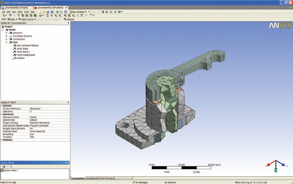 The sectioning tools in ANSYSWorkbench 11 allow you to inspect the internal structure of your mesh. |
ANSYS Workbench is not a product as such — you’ll never hear an ANSYS rep trying to sell it to you. ANSYS Workbench is a platform through which you communicate and interact with the wealth of technology that ANSYS has at its disposal. Because it can be applied to a huge range of simulation tasks, it is perhaps best to walk through a generic workflow to see how ANSYS Workbench creates a common platform that provides the basics of the data access and presentation.
Looking at the UI, ANSYS Workbench displays simulation data in a hierarchical tree that separates the various groups of inputs and outputs. Your model data is stored at the highest level and this level contains the geometry that your mesh is built on, contacts, mesh, and the environment in which you are operating. The mesh is the elemental representation of your parts (the precise nature of this mesh will change depending on your task) and all are held within this folder.
Workbench allows you to intelligently refine your mesh by starting with a coarse mesh. You can find areas of high-stress concentration, then re-mesh using a much higher density mesh to increase accuracy. The system can handle much of this automatically but you can also dive in and interactively re-mesh with more detail.
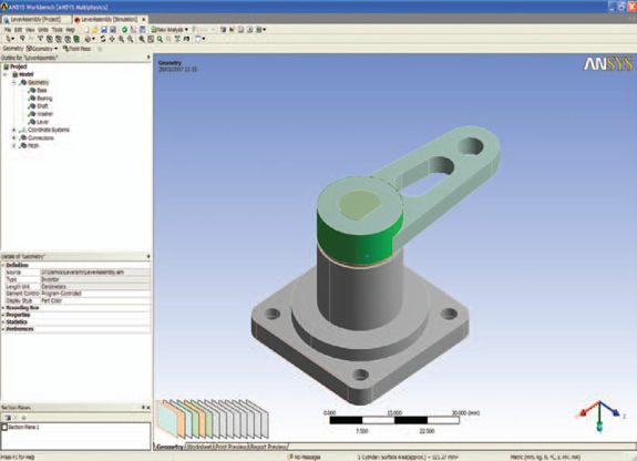 The selection tools with Workbench allow you to ensure that you’re selecting the correct geometry when applying boundary conditions. |
The Workbench UI system is built on the standard interaction methods now common in this class of tool. Everything is geared toward making model and study interaction much more efficient, with many processes applied directly to the model with dynamic feedback, rather than through obscure dialogs. There are also some very neat little UI tricks that are worth a mention: when you have a 3D model loaded, the system shows you an OS map-like scale that gives you an indication of the scale or overall dimensions of the model you’re working with. While this might sound odd, when you consider that many systems don’t hold unit data and you have to specify it on import, it’s a useful clue to show if you get that wrong.
Elsewhere, selection of geometry is frequently tricky as you’re often looking to apply loads and such to surfaces or faces that share common space. Workbench displays a graphic at the bottom that shows a number of 3D planes. As you hover over each plane with the mouse, the corresponding color-coded (according to part color) 3D plane is highlighted.
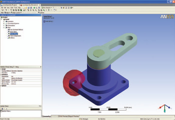 The interactive mesh refinement tools allow you to select areas of stress concentration to improve the resolution of the simulated model. |
Geometry Definition
The starting point for any simulation task is a geometry file and this can be sourced in several ways. The first method is to use the CAD connections, which allow you to read native data — Pro/Engineer, SolidWorks, NX/Unigraphics, CATIA V5, Inventor, etc. — alternatively, IGES, STEP, ACIS, or Parasolid. Data is read into the Workbench fairly intelligently to preserve part names. If it’s Inventor, Pro/E, or NX, a sub-set of material definitions is also preserved including Young’s Modulus, Poisson Ratio, Mass Density, Specific Heat, Thermal Conductivity, and Thermal Expansion Coefficient. One thing to note is that the system doesn’t replicate assembly structure information, so any nested subassemblies will be flattened out — a potential problem for those working with complex product models.
During the input process, the system will also interrogate the assembly and define any points of contact it finds. Now, it’s important to note that this is not read from the assembly mates, but applied in Workbench. The system defines any contact found (within a tolerance) as static, but it’s a simple case of using the Details Pane to edit their definition. As standard, you can apply static, rotational, friction-based contact within your model with ease. Alongside CAD import, the DesignModeler tool allows you to take data from a variety of sources, fix it if need be, integrate it into a single cohesive whole, and use that as you would native information.
Data Abstraction & Reconstruction
ANSYS Workbench has a set of tools that can be used to repurpose or abstract your CAD geometry for a number of reasons, whether to repair problems or to find and remove features (such as holes, fillets, and chamfers) that have little or no influence on the performance of your part. Finally, the new FE Modeler tool allows you to work with legacy or third-party FEA data for which there is no CAD base. It allows you to read data decks from a wide variety of sources (ABAQUS, NASTRAN, and ANSYS CDB files), inspect the mesh, find areas in which explicit surfaces can be placed and create them. It’s ideal for finding prismatic surface types, such as planar faces, cylinders (such as holes), pockets, cuts, spherical features, and such. Those which can’t be handled (such as complex surfaces) are approximated into freeform NURBS. The end result is a surface model that can be used to then regenerate the mesh according to your requirements and adapted to your needs — all from a seemingly static, non-editable mesh format.
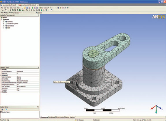 This image illustrates the resultant refined mesh for better suiting this simulation’s load case. |
Materials Definition and Reporting
As you would expect, ANSYS Workbench is supplied with a range of standard materials, as you would get with any FEA-based system. But as always you’ll want to adapt them. The system uses a central, XML-based material database to store and distribute materials. You start a new material and add all of the standard values (minimum of Young’s Modulus required, if not specified; Poisson’s ratio is assumed) for structural, thermal, and electromagnetic performance. You can then add properties to add more advanced functions of material. The whole process is completed with a great deal of feedback.
Report generation is common in mainstream simulation tools, but I’m not going to pretend your reports are going to just consist of a template-based output from a CAD system. The point is that they get you a large part of the way there, quickly. ANSYS has always been a little better than others and creates reports based on a wizard-style workflow, so you define the various inputs (title, description, etc.) and the system handles the rest. It allows you to create diagrams at any point, so the graphics window and a caption is stored and then added to the report. This contains a complete documentation of your analysis study (materials, inputs, as well as results), all within a neat hyperlinked format. When you hit the Generate Report button, the whole thing is compiled for you and stored in a HTML format. It can also be output to Word or PowerPoint files directly.
Mechanisms
One of the key areas for this release relates to mechanisms. While computation technology has advanced, the fact is that mechanism simulation combined with how the forces are manifested within the constituent parts is still a complex process. ANSYS works around this by allowing you to model both rigid and flexible bodies in one environment intelligently.
To do this, the motion analysis is set-up and run as normal. At that point, the system exercises the joints according to your inputs to gain the force load transfer conditions using the Rigid Body solver. Once that is complete, you switch those appropriate parts to flexible and carry out the Rigid Dynamics Solve to find out how those key parts perform under loading conditions using stress analysis. Results can be created at any time step and you have all manner of tools to inspect the loading and subsequent stress and strain values.
Design optimization — DesignXplorer
Alongside the basics of simulation, ANSYS has always been active in optimization. While it’s possible to conduct optimization using traditional FEA, with today’s processing technology enabling the user to conduct simulation tasks more efficiently than ever before, doing this type of work manually isn’t feasible. Thus, we need to work smarter, and Workbench allows you to do this.
Within your CAD system, you add a prefix to the controlling parameter within your CAD model (_DS is the default). This prefix then exposes your model to Workbench. You then create the input value ranges in which these parameters are varied — either manually or in a design of experiments manner to specific values. You then add the loads and restraints as normal. Output parameters (the things you’re looking to optimize) are also added, whether that’s deformation, maximum and minimum stress or strain value. Design Points, which are effectively sensors or gauges on your mesh, can also be added so that you can track output values (such as stress, strain, deformation, etc.) as the solution is calculated. You can use Design Points to find values within the postprocessing reporting stage. The system then connects to the CAD tool, generates the model, builds the mesh, solves, and captures all of the data within Workbench.
Once completed, you have the ability to work through a whole host of tools to gauge the performance of each iteration. All manner of reporting tools within the system are available here, but adapted to allow for the simultaneous visualization and inspection of multiple datasets on screen at once (with synchronize model manipulation and all that good stuff). The system also includes a number of formalized tools to carry out additional work with this mass of data, such as What if and Deterministic studies, as well as Six Sigma and Robust Design tasks.
A Unified Environment
ANSYS Workbench provides a unified environment in which you have access to a massive amount of simulation functionality. It allows the user to take 3D-based processes to their next logical conclusion — that of using that rich definition of a product under development and use it as the base for simulation, and perhaps just as importantly, optimization. By carrying out more holistic simulation of all areas of a product’s performance and function, we can build products that are of higher quality, cost less, and are more suitable for their intended purpose.
ANSYS Corp.’s acquisitions mean it has a huge arsenal of simulation technologies ranging from its core-mastery of structural FEA analysis, through various forms of CFD (both with the CFX and more recent Fluent acquisition) and into newer, less recognized fields. For example, the Autodyne technology allows the user to carry out explicit analysis over a very short timescale using a variety of meshing and solver technologies. What’s more, each simulation technology has been acquired with a clear, long-term strategy in mind: to provide leading, full-spectrum simulation technologies within the fully integrated Workbench environment.
If you’re looking to integrate your CAD use with simulation, then you’d be hard-pressed to find a system that provides more in terms of both functionality and the ease of use factor that’s essential to making the technology usable as part of your product development process.
ANSYS Workbench 11
ANSYS, Inc.
Canonsburg, PA
Al Dean is technology editor at MCAD Magazine, a UK product development and manufacturing technology journal and is editor of Prototype magazine. You can send comments about this article through e-mail to [email protected].

DE's editors contribute news and new product announcements to Digital Engineering. Press releases may be sent to them via [email protected].
Follow DEJoin over 90,000 engineering professionals who get fresh engineering news as soon as it is published.


About Us · Contact Us · Editorial Team · Advertising · Privacy Policy · Subscriber Services · © 2026 Digital Engineering 24/7 · Peerless Media