Helping design and engineering professionals discover, evaluate and specify technologies and processes that shorten the design cycle and enable success.
Alert!
Digital Engineering ceased publication on July 1, 2026. This website remains available as an archive of engineering content.
For inquiries or information, please email [email protected].

May 2026 Special Focus: Artificial Intelligence in Design and Simulation
In this Special Focus Issue, learn about the latest developments in the integration of artificial intelligence into engineering workflows.

Design & Simulation Software Guide 2025
In this Special Issue, Digital Engineering presents its second annual guide to design and simulation software vendors.
The military’s advanced concept ejection seat ACES II (Figure 1) is one of the most successful aircrew escape systems in U.S. Air Force history and is credited with saving more than 456 lives since it was introduced in 1976. With more than 8,000 seats delivered to date, the ACES II is currently used on F-15, F-16, B-1B, B-2, A-10, F-117, and F -22 aircraft.
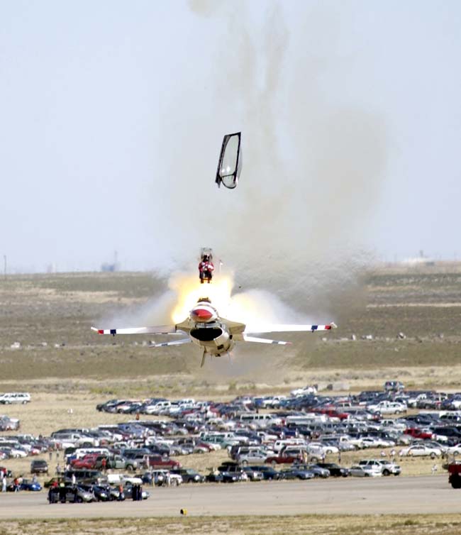 Figure 1. With this ejection seat, used in emergency situations in military aircraft, an explosive charge or rocket motor thrusts the seat out of the aircraft, carrying the pilot with it. Once airborne, a parachute is deployed. This photo shows the ACES II ejection seat. (Courtesy of U.S. Air Force. Photo by Staff Sgt. Bennie J. Davis III.) |
Using the strengths of the ACES II as a foundation, Goodrich Aircraft Interiors and Concurrent Technologies Corp. (CTC), both in the U.S., developed the next-generation ACES 5 seat for the F-35 Joint Strike Fighter (JSF). The new seat was optimized to enhance aircrew safety, reduce maintenance downtime and weight, and integrate with the F-35 cockpit. The biggest challenge, however, was developing and delivering a brand new seat structure in less than 14 months.
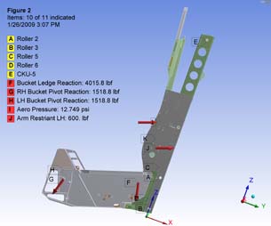 Figure 2. This illustration shows the loads imparted on the seat when it is ejected from an aircraft, traveling at 750 mph. |
Overcoming Challenges
The parametric link between the ANSYS Workbench platform and Pro/ENGINEER Wildfire software was a critical factor in successfully developing a design that met all the requirements while maintaining the aggressive schedule. Engineers at CTC were able to quickly update simulations for multiple design iterations. This concurrent design and analysis approach enabled the team to optimize the seat for both function and weight from the earliest developmental stage.
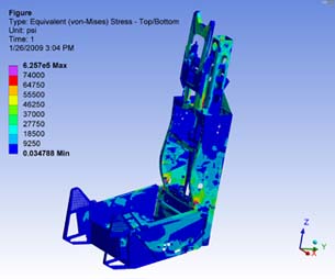
Analysis of the seat was split into three phases. The first analysis phase was conceptual design development. During this time, engineers designed the seat structure to meet functional requirements, and simulation was used to verify that the structure was sound and weight was optimized. Functional, structural, and safety requirements were derived from the performance-based specification supplied by aircraft manufacturer Lockheed Martin for the JSF ejection seat. To reduce maintenance downtime, a modular seat structure was developed to allow the seat to be easily removed from the aircraft. The modular seat consists of the seat back, seat bucket, parachute, survival kit, and aircraft interface module. Engineers reduced assembly costs and the part count by designing the new seat to use a few machined components instead of many sheet metal components, and they evaluated designs for tough load requirements (e.g., ejection from an aircraft traveling at 750 mph), parachute load, and crash loads (Figures 2 and 3).
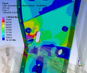
The first simulation phase evaluated individual components of the preliminary seat design. Equivalent stress plots of various stages (Figure 4) of the bucket design evolution demonstrated how, during ejection, the occupant’s legs are forced apart by the windblast. The structure had to be optimized to contain this splitting force, or else the occupant would sustain critical injuries. The engineering team analyzed the structure for ejection and crash loads within the ANSYS Workbench framework. Once the simulation was set up, design iterations were quickly evaluated for all the applicable load cases simply by updating the geometry from the CAD system.
|
During the second analysis phase, the CTC team built a system model of the seat structure. Analyzing the seat structure as a whole gave the most representative view of how the actual seat structure would behave and eliminated compromises associated with analyzing individual seat subsystems or modules. To prepare the system model for analysis, the team imported the CAD geometry into the ANSYS DesignModeler tool, where defeaturing operations (e.g., elimination of rivet holes) were performed. In addition, a few components were converted to mid-plane surface models, using the software’s automatic mid-plane feature.
The CTC team assigned material properties, defined boundary conditions, and applied loads to the system model. Contact regions were characterized for each riveted face on the seat. This allowed contact reaction forces to be used to determine the number of rivets required at each joint. Point masses were used to represent nonstructural seat subsystems, such as the parachute and survival kits.
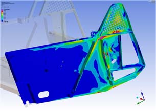 Figure 4. This illustration shows equivalent stress plots from various iterations of the ACES 5 ejection seat bucket design. The weight of the bucket, one of the design considerations, is shown for each. | 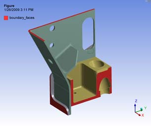 Figure 5. This submodel, created in ANSYS DesignModeler, indicates high-stress regions. The cut boundaries are shown in red. |
The model was meshed using a hexdominant mesh control and a 0.125 in. global element size. A single linear static structural analysis of the seat model was solved in less than 30 min., using the direct solver in the mechanical software, available through the ANSYS Workbench platform. The quick analysis turnaround time allowed the engineering team to quickly evaluate various what-if design scenarios.
Actual loads on the seat are dynamic in nature, and the seat will experience these loads only one time during deployment. Because the system model used a static simulation approach without nonlinear material properties, the simulation revealed small areas of stress concentration that exceeded the allowable ultimate strength of the material. Engineers scrutinized these high-stress zones using submodels that allowed material yielding during the third phase of the analysis.
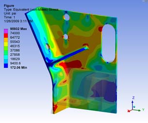 Figure 6. These submodel results provide more-accurate stress results than the global static model. |
To produce the submodel, the team first cut out the area of interest, using the ANSYS DesignModeler tool. The CTC team developed a submodeling subroutine, using the commands object in the mechanical simulation area of ANSYS Workbench. The subroutine interpolated the system model displacements onto the submodels’ cut boundaries (Figure 5). The submodel results typically showed that some permanent deformation occurred, but the ultimate strength of the material was not exceeded. Furthermore, the submodel provided more accurate stress results due to the finer mesh (Figure 6). Roughly 30 high-stress areas were evaluated using this technique to ensure that the structure would not fail when loaded in extreme conditions. These results proved that the ultimate load requirements were met.
An Extraordinary Outcome
After 10 months of development, five prototype seats were built for test purposes, and the first ejection test of the ACES 5 F-35 JSF seat occurred after 14 months. The seat performed flawlessly the first time out.
This extraordinary outcome is the result of a great deal of teamwork between Goodrich and CTC. The results would have been unattainable without using engineering simulation software.
More Info:
ANSYS
Canonsburg, PA
Concurrent Technologies Corp.
Johnstown, PA
Goodrich Aircraft Interior Products
Phoenix, AZ
Lockheed Martin
Bethesda, MD
Parametric Technology Corp.
Needham, MA

DE's editors contribute news and new product announcements to Digital Engineering. Press releases may be sent to them via [email protected].
Follow DEJoin over 90,000 engineering professionals who get fresh engineering news as soon as it is published.


About Us · Contact Us · Editorial Team · Advertising · Privacy Policy · Subscriber Services · © 2026 Digital Engineering 24/7 · Peerless Media