Helping design and engineering professionals discover, evaluate and specify technologies and processes that shorten the design cycle and enable success.
Digital Engineering April 2026
In the latest issue of Digital Engineering, we take a look at the latest innovations in design for additive manufacturing, including the use of natural language inputs, social media cosplayers, and AI integration. The issue also includes a feature…

January Special Focus Issue: Design for Additive
In this Special Focus Issue of Digital Engineering, learn about the latest advancements in design for additive manufacturing, including new software tools, additive in automotive, custom medical devices, and more.
3D printed parts are becoming a regular feature of familiar objects, from airplanes to digital cameras. Like every other manufactured part, they, too, are liable to wear and tear over time, and prone to cracks from pressure and abuse. Whatever the application may be, the lifespan of a 3D-printed part is much harder to determine, because its production involves novel materials and methods. In this article, we look at the science of simulating and predicting the fatigue life of additive manufactured (AM) designs.
Allin Groom, principal research scientist at Autodesk Research, is a material scientist. He wrote his PhD thesis on the lifespan of manufactured parts. In a previous Autodesk TechX talk, Groom, along with Dagmara Szkurlat, Autodesk research manager, gave a presentation on the use of generative design to extend the fatigue life of a rotor component for an unmanned aerial vehicle.
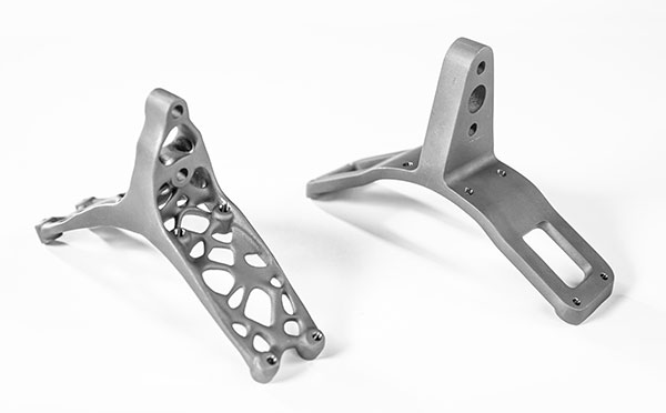
In material science, fatigue is the weakening of a material caused by operational cycles, leading to cracks and separations. Going beyond the typical generative design targets (commonly, mass and weight reduction), Groom and his team aimed to optimize the part for fatigue-safe life and fatigue-damage tolerance.
“We knew we could reduce the part’s mass with generative design, but we needed it to last a certain number of operational cycles. The target was 300,000 cycles. But we were able to achieve 314,000 cycles,” recalls Groom.
The part was a 3D printed part produced in laser powder bed fusion (PBF), using Titanium6 (Ti6). Groom and his team had to take into account the anisotropic nature of 3D printed parts while exploring the design options in Autodesk Fusion. Since 3D-printed parts are manufactured layer by layer, the Z direction’s strength tends to be their vulnerability.
“With some alloys, we knew if we generated the part using the Z orientation, we had to treat it differently from those in other directions. But this alloy wasn’t particularly sensitive to that. We did tests to verify that. The other thing we had to pay attention to was the surface finish. In a laser PBF part, the surface roughness could be detrimental to the part’s performance,” notes Groom. “But we were able to show that with Ti6, surface roughness was not susceptible to cracks. With that knowledge, the manufacturer could ignore the usual post-processing requirements, such as machining and polishing.”
The attitude of the airline industry’s regulatory bodies toward AM parts is also evolving. “Physical testing supersedes all other forms of evidence,” notes Groom. “But the critical nature of the part is also a consideration. A critical airframe component would always require solid proof, especially if made with new materials. But for noncritical components, I suspect simulation would, in time, become acceptable proof.”
AM technology has also reached a level of maturity that warrants trust, as Groom sees it. In its early days, many vendors and researchers focused on simulating the AM process itself to gain insights into its reliability. “But we now have a reproducible, repeatable process, so simulation’s focus should shift from build preparation to the performance of the built part,” Groom reasons.
The Ti6 material used in this project took roughly 50 years to develop. “That’s because we need a good understanding of its thermomechanics to be able to melt it into large billets that can be rolled without cracks and heat-treated,” says Groom. He believes AI and machine learning is about to accelerate the development of new AM materials.
“The old way of doing things is like navigating with a hand-drawn pirate map,” he quips. “The new way is like using Google Maps. We’re going to soon see new alloys we’ve never seen before.”
Bart Van der Schueren, chief strategy and technology officer, Materialise, explains how metal used in AM is different from metal used for traditional manufacturing. “For example, the 316 L stainless steel you can get in bulk is not the same as the 316 L used in 3D printing,” he says. “We recognized that. That’s why, over the years, we have been collecting the mechanical properties of the parts we have been making. So we now know the mean value for the tensile strength of these materials.”
However, the mean value is simply the base line. For parts to be used in general applications where failure does not jeopardize lives and limbs (such as a button on a DSLR camera), a tensile strength below the mean value is usually acceptable. In contrast, for parts deployed in critical applications (such as airplane parts for takeoff and landing), the strength should be higher than the mean. “To determine that, you need to know the Gaussian distribution around the mean value. We have this information available in our manufacturing units,” says Van der Schueren.
What happens to metal in the AM process is relatively straightforward to simulate, compared to polymer and plastics, Van der Schueren notes. “With metal AM, it’s essentially a welding process where you stack up the layers and let them cool down,” he explains. “With polyamide or plastic materials, first you heat it up close to the melting point, where the characteristics of the material change. Then during the cooling process, a recrystallization process happens, which changes the material again. That process may start a few minutes after your printed part has cooled down. That is extremely difficult to simulate. I don’t know of any simulation engine that can accurately replicate that.”
Chris Robinson, senior product manager for Additive Manufacturing, Ansys, similarly notes, “Simulating metal AM is much easier, but in Fused Filament Fabrication (FFF) with plastics and polymers, there’s a wide range of glass-transition temperatures it’s subjected to, like putting goo on top of goo. It’s difficult to understand how much surface connection you’re getting in the build direction.”
The more advanced use of AM to predict and simulate the failure of 3D printed parts may involve assigning different properties to different regions of the part, to better reflect the part’s thermal history. “Whereas the microstructure of wrought materials is pretty consistent, AM materials go through changes based on their thermal history. With Ansys mechanical, based on the thermal profile of a part, you can identify regions that will have more pores. It’s something you can include in fatigue modeling,” Robinson says. “You can also add CT scan data or in situ measurement data into your model.”
Commonly used AM materials are already part of Ansys software, ready for you to select from a library. “We did lots of testing and validation to develop these material models,” says Robinson. “You can also access the Granta material models that have a different level of depth and data. Of course, we also recognize new materials are developed and introduced every day, so if you have empirical data from a testing house, you can enter them too.”
In 2018, Ansys and Granta, a spinoff of the University of Cambridge’s Department of Engineering, entered a collaborative engagement. A year later, in 2019, Ansys acquired Granta, allowing it to incorporate the latter’s data into its software packages.

Materialise is headquartered in Leuven, Belgium and has branches worldwide. We've been playing an active role in the field of Additive Manufacturing (AM) since 1990. In addition to having the largest single-site capacity of AM equipment in…
Kenneth Wong is Digital Engineering's resident blogger and senior editor. Email him at [email protected] or share your thoughts or suggestions at digitaleng.news/facebook.
Follow DEJoin over 90,000 engineering professionals who get fresh engineering news as soon as it is published.


About Us · Contact Us · Editorial Team · Advertising · Privacy Policy · Subscriber Services · © 2026 Digital Engineering 24/7 · Peerless Media