Helping design and engineering professionals discover, evaluate and specify technologies and processes that shorten the design cycle and enable success.


Alert!
Digital Engineering ceased publication on July 1, 2026. This website remains available as an archive of engineering content.
For inquiries or information, please email [email protected].

May 2026 Special Focus: Artificial Intelligence in Design and Simulation
In this Special Focus Issue, learn about the latest developments in the integration of artificial intelligence into engineering workflows.

Design & Simulation Software Guide 2025
In this Special Issue, Digital Engineering presents its second annual guide to design and simulation software vendors.
Leading manufacturers are abandoning the old serial design system in which various functions work along a continuum in favor of a multi-disciplinary product design process that requires successfully integrating multiple authoring systems and processes. For example, the number of electronic components in cars has grown drastically; electronics now account for 35-40% of a car’s cost, for example, the Mercedes-Benz S-Class has 140 ECUs. Designers need access to multiple tools across mechanical and electric/electronic domains to ensure a timely delivery of products that meet with customer specifications. This highly complex environment requires a high level of interdependencies to function effectively.
Despite this complexity, manufacturers that are taking advantage of simulation tools such as frontloading computational fluid dynamics (CFD) have discovered that they don’t need to reimagine or change their engineering process to benefit. While many organizations thought it would be more convenient to use existing tools, they quickly realized that they were forcing their teams to use the wrong tools. The key success factor is selecting the right solution that offers the right combination of application-specific functionality and fits into existing engineering processes without any disruption.
The new empowered engineer requires a different set of engineering tools for CFD, and these are some of the questions to ask when looking for a thermal simulation solution:
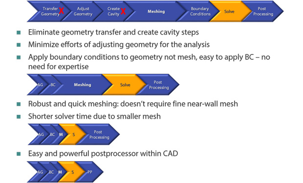 Frontloaded CFD solutions offer significant time savings during pre processing.
The CFD software makes it relatively easy to conduct what-if tests. Product designers can create multiple variations by modifying a solid model, which can then be analyzed without having to reapply loads, boundary conditions, and material properties, for example. The results can then be compared among the many design options to choose the best possible one.
This type of tool enables product designers to accelerate key decisions at their workstations as they experiment with design scenarios and as they hone in on the best, most efficient, reliable, and cost-effective design. This intuitive virtual prototyping process allows designers to optimize a product during the design stages, with that first physical prototype often being the design that goes into final manufacturing, delivering the best design at lower cost (because of fewer physical prototypes), and getting it to market faster than ever before.
The following is an example of how this workflow can be put to good use.
Bucher Hydraulics Division produces valves mainly used in mobile applications in construction and agricultural machinery but also in wind turbines and industrial applications such as plastic injection machines. Bucher Hydraulics AG Frutigen, located in the Bernese Oberland region of the Swiss Alps, is one of the company’s six competence centers and specializes in cartridge and customized valves and valve manifolds. Each competence center is responsible for a separate area: design/layout/construction, prototyping and testing, serial production, sales and after sales.
In the past, when Bucher Hydraulics engineers built small- and medium-sized valves, they were able to obtain test results and optimize the products in a short time at reasonable costs from their prototyping and testing competence center. They didn’t need to use flow simulation because they were able to quickly use real results.
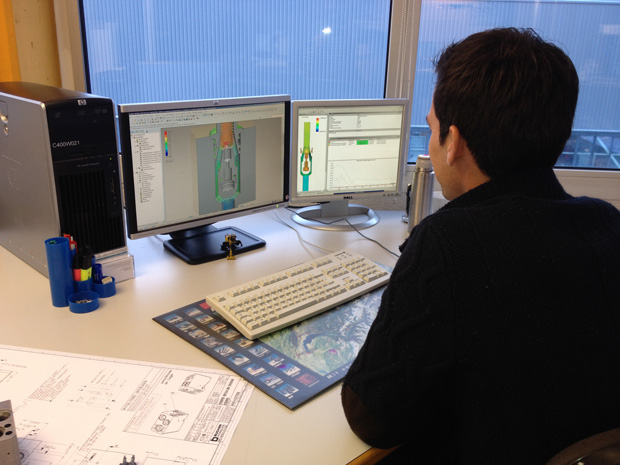
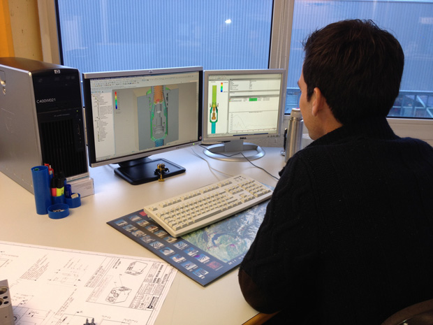 FloEFD can be used easily by design engineers within their MCAD environment. Image courtesy of Bucher Hydraulics.
But today’s projects are for valves that deliver high flow and pressure at very low pressure drop within small dimensions. For these housings or manifolds, all the CFD calculations were being done at a specialized competence center. This was causing delays because of handover from the designer to the operator (preparation of data files and explanation of the task), handover from the operator to the designer (visualization of the results and its explanation) and task misunderstandings and interpretation that would lead to several repetition loops. The team was working with four different software programs for modeling, meshing, calculation and visualization, which needed dedicated people to use and maintain daily.
They wanted simulation and testing software that would be easy to learn and easily used by the valve designer who would not be working with it all of the time. They also wanted quick and precise results with good and simple visualization, simple use of their existing 3D CAD data, and a simple data repository that would include variants.
After reviewing their options, they chose FloEFD for Creo because it enabled engineers to conduct fluid flow analysis inside the PTC Creo MCAD environment and to simulate their designs quickly, efficiently and early in the process.
They found that the layout of valves is much better, especially in regard to performance and costs, because they can analyze more variations in the amount of time it used to take to analyze a conventional design without CFD. Their first design is much closer to the target, and optimization of the prototypes is much more efficient with FloEFD. Because of the good results and availability, they use FloEFD for the design of new products in addition to optimizing existing valves.
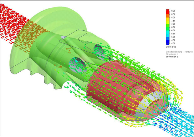 Analyzing versions and running through what-if scenarios is much easier and faster in FloEFD for Creo. Image courtesy of Bucher Hydraulics.
Time is of the essence in today’s global marketplace, and by enabling design engineers at Bucher to conduct what-if analysis and progress their designs quickly, the company is able to provide products that offer a great combination of functionality and high reliability with a great price performance ratio.
More Info


Join over 90,000 engineering professionals who get fresh engineering news as soon as it is published.






About Us · Contact Us · Editorial Team · Advertising · Privacy Policy · Subscriber Services · © 2026 Digital Engineering 24/7 · Peerless Media