Helping design and engineering professionals discover, evaluate and specify technologies and processes that shorten the design cycle and enable success.
Alert!
Digital Engineering ceased publication on July 1, 2026. This website remains available as an archive of engineering content.
For inquiries or information, please email [email protected].
Sponsored
 Dear Desktop Engineering Reader:
Additive manufacturing (AM) processes may seem to have similar ways of making things, but each produces unique parts with specific characteristics. For you, this means you need a different mindset as you design and prepare parts for AM fabrication than if you were working with injection molding. To obtain your desired results, you need to consider how the AM build technology operates and how the build materials behave. Today’s Check it Out link takes you to a fine resource on designing for FDM (Fused Deposition Modeling) technology.
Weighing in at just four pages, “Fused Deposition Modeling — FDM — Design Guidelines” from Stratasys Direct Manufacturing is succinct in every way. It spends no ink explaining what, say, an undercut does. Still, this new white paper is not a doctoral thesis, although it does require more than a functional literacy of the core concepts of the design for manufacturing process.
This paper is intended to be a brief reference guide to what you need to know and do to get good results from an FDM fabrication process, especially a process run by a third-party service bureau like Stratasys Direct Manufacturing. That said, much of the data conveyed benefits anyone designing for an on-site FDM-based system. If you’re considering using FDM services from Stratasys Direct Manufacturing, the quality of this paper should give you high confidence in what they can do for you.
So, what’s inside? Well, first remember that FDM technology extrudes heated thermoplastics to build parts layer by layer. So, you’re talking hot flowing plastic, and that might get you thinking about issues like shrinkage and warp. Only, FDM is not injection molding, so it tosses some curves at your molding experience. Shrinkage and warp, for example, are not an issue with FDM, unlike injection molding or even other 3D printing technologies. And here’s the entire discussion of draft angles: “Draft is unnecessary in FDM parts.”
You get insights on how to handle holes, threads and pin sizes. Throughout, you’ll find all sorts of tips and tricks on issues like part sizes and orientation, sectioning, assemblies, bosses and hinges. Where necessary, simple but concise illustrations demystify complex details.
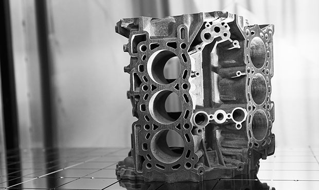 A plastic part fabricated by Fused Deposition Modeling (FDM) technology. Image courtesy of Stratasys Direct Manufacturing.
The nub of the matter is that “Fused Deposition Modeling — FDM — Design Guidelines” is a handy resource that you’ll likely return to again and again. And with the increasing use of FDM-made parts for end-use components that characteristic makes this paper a must-have. Hit today’s Check it Out link and download your complimentary copy.
Thanks, Pal. – Lockwood
Anthony J. Lockwood
Editor at Large, Desktop Engineering
Download "Fused Deposition Modeling — FDM — Design Guidelines" here.

Anthony J. Lockwood is Digital Engineering's founding editor. He is now retired. Contact him via [email protected].
Follow DE


About Us · Contact Us · Editorial Team · Advertising · Privacy Policy · Subscriber Services · © 2026 Digital Engineering 24/7 · Peerless Media