Helping design and engineering professionals discover, evaluate and specify technologies and processes that shorten the design cycle and enable success.

May 2026 Special Focus: Artificial Intelligence in Design and Simulation
In this Special Focus Issue, learn about the latest developments in the integration of artificial intelligence into engineering workflows.

Design & Simulation Software Guide 2025
In this Special Issue, Digital Engineering presents its second annual guide to design and simulation software vendors.
In one fabrication, the fiber-layered prepreg is added in the mold by thermoforming as an insert. Then, a back injection is performed to attach structural functional structures to the prepreg while maintaining lightweight properties (Fig. 1).
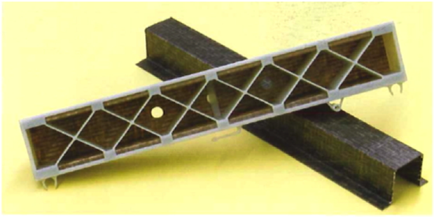 Fig. 1. A composite sheet product made by thermoforming and back injection
The composites molding process mentioned here is called two-step over molding. It usually consists of (1) draping process of a fiber prepreg; and (2) back injection. The shaping of a prepreg is done first by soaking a dry fiber fabric in the resin under room temperature, then put it under low temperature and freeze it into a fiber prepreg. Next, the solid and flake prepreg will be moved into the mold by robotic arms, and the draping process will proceed accordingly.
The main goal of draping process is to shape the laminated fiber mat. The fiber prepreg will be heated and will soften through infrared radiation and then be compressed and solidified. After the prepreg is shaped, plastic melt will be injected into the mold. The molded product will consist of two parts: (1) continuous fiber prepreg; and (2) plastic molded part. A major issue in this case is to effectively predict the product properties that combine these two parts.
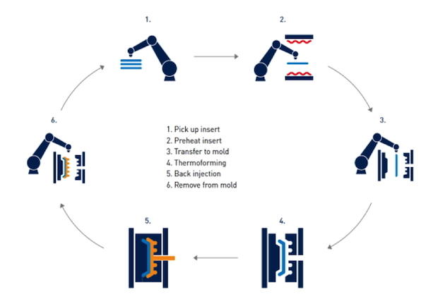 Fig. 2. Two-step over molding process.
Moldex3D R14 version has integrated with LS-DYNA’s draping analysis to simulate the deformation behavior. The fiber mat orientation of the fiber prepreg after the draping process can be considered in Moldex3D’s analysis for the subsequent molding process to obtain a more comprehensive warpage analysis of the composites product. LS-DYNA focuses on analyzing the deformation behavior of a continuous fiber in compression molding. Moldex3D will incorporate LS- DYNA’s calculation of prepreg deformation and consider the product geometry and continuous fiber mat orientation analysis as the parameters of a part insert. In Moldex3D’s filling analysis, it will consider the prepreg geometry and its material characteristics as the boundary conditions and in the subsequent warpage analysis, it will consider the insert as a continuous fiber composite material and perform a deformation analysis of a multi-component part (Fig. 3).
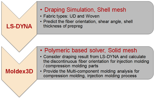 Fig. 3. Integrated analysis for two-step over molding process between Moldex3D and LS-DYNA
Fig. 4 is Moldex3D’s case study example. The plastic structure part is molded on top of the fiber prepreg; Moldex3D is used to conduct the filling, packing and then the warpage analyses with the consideration of continuous fiber mat orientation.
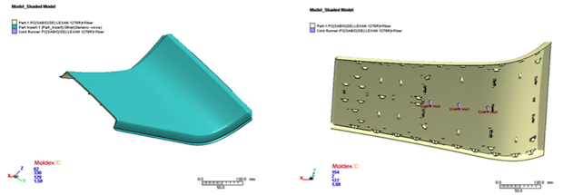 Fig. 4. Different geometries for two-step over molding process
Through Moldex3D’s Multiple Component Molding feature, the fiber mat orientation predictions of a uniaxial prepreg in three different directions can be analyzed, and the product’s strength variations of different directions can be attained. As shown in the analysis results, the deformation in the Z axis is the largest when the fiber mat orientation is at the angle of 45°. The least deformation occurs when the fiber mat orientations are at 0° and 90° with the deformation at 90° being the most ideal.
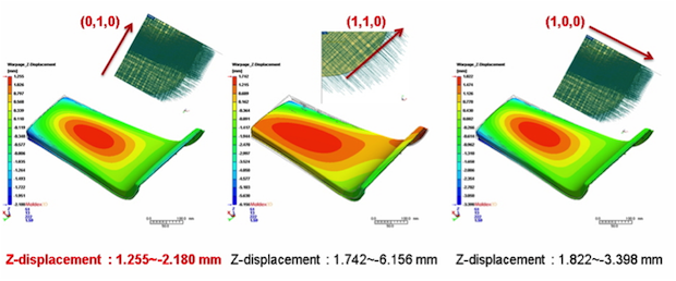 Fig. 5. The warpage predictions for different fiber mat orientations of prepregs
Moldex3D’s filling analysis considers the effect of chopped fiber orientation in the subsequent plastic molding process and is able to observe the influences of the plastic material and the chopped fiber orientation. In this case, the influence of the plastic material to the warpage is more significant; it causes greater shrinkage in the Y direction. When the fiber mat orientation is at 90°, the shrinkage can be compensated, making it the least deformed design.
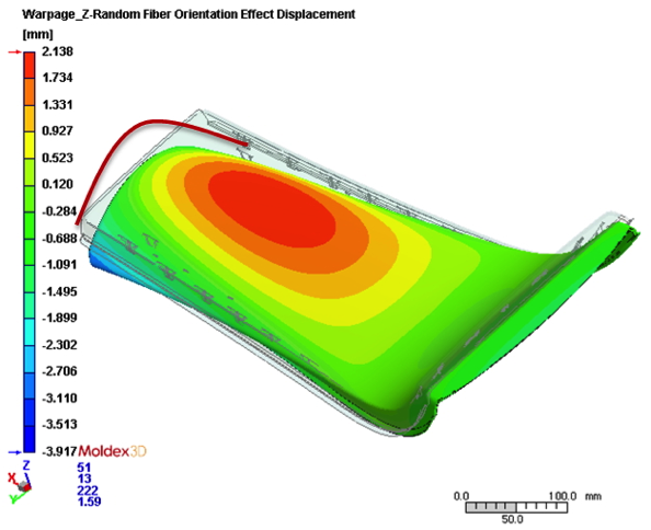 Fig. 6. Moldex3D can predict the warpage behavior of the injected structure part.
With this case, we can understand the continuous fiber prepreg orientation and non-isotropic chopped fiber in two-step over molding will affect the product warpage. Furthermore, we find that fiber mat orientation is the main contributing factor of the product warpage. Moldex3D’s analysis provides great insights for its users in the planning of two-step over molding process and helps avoid excessive warpage to ensure the success of their composite products and assist users in maximizing their advantages.
Sources: This article was submitted by CoreTech System Co., Ltd., which develops Moldex3D.

DE's editors contribute news and new product announcements to Digital Engineering. Press releases may be sent to them via [email protected].
Follow DEJoin over 90,000 engineering professionals who get fresh engineering news as soon as it is published.


About Us · Contact Us · Editorial Team · Advertising · Privacy Policy · Subscriber Services · © 2026 Digital Engineering 24/7 · Peerless Media