Helping design and engineering professionals discover, evaluate and specify technologies and processes that shorten the design cycle and enable success.
Alert!
Digital Engineering ceased publication on July 1, 2026. This website remains available as an archive of engineering content.
For inquiries or information, please email [email protected].


May 2026 Special Focus: Artificial Intelligence in Design and Simulation
In this Special Focus Issue, learn about the latest developments in the integration of artificial intelligence into engineering workflows.

Design & Simulation Software Guide 2025
In this Special Issue, Digital Engineering presents its second annual guide to design and simulation software vendors.
 At the recent NAFEMS Americas conference in Seattle, I had a chance to talk to analysts and designers about what role structural analysis can play in design. The need to distinguish between the influences of stiffness and strength was apparent. This was best summed up by an ex-colleague who recounted the tale of the “repair scheme death spiral.”
Imagine two parallel vertical tubes, each connected at top and bottom between two stiff horizontal beams. The beams are being pulled apart vertically, so that equal vertical load is induced in each tube. A fatigue crack occurs in one tube and the repair scheme calls for a reinforcing strap to be bonded over this region. The net axial stiffness, (EA/L), of the reinforced tube is now higher than the undamaged tube. E is Young’s Modulus, A is cross sectional area and L is effective length.
In a configuration like this, the load will be distributed between the two tubes in proportion to their axial stiffness. So the stiffened tube attracts the bigger share of the load. Eventually, this additional load results in further fatigue cracking and a new repair is called for. This repair adds further stiffness. This attracts more load to the repair, at the same time lowering the stresses in the healthy tube. You can guess how this goes: Eventually the massively stiff repaired tube is carrying the bulk of the load, while the healthy tube is made redundant.
Ideally, a dummy repair patch would be added to the intact tube, so that the stiffness is always the same between the two, and hence the load is distributed evenly.
It is an exaggerated story, but illustrates the point that designs should first be assessed for relative stiffness of each load path. This will determine the load level in each path. The strength of the structure along that load path is then a function of the local stresses that will occur. Design for strength should come secondly as a local assessment. If the load path is under-strength, revising stiffness (perhaps reducing material) may be a more attractive option than increasing strength (by adding material). The only case where strength will dictate a load path is after material yield or local buckling, when it is too late!
The structure shown in Fig. 1 has a defect on the right hand side leg, which has been dressed out to a constant radius notch. This is the starting point for a repair. Two repair options are considered. In the first, shown in Fig. 2, a doubler repair patch of equal thickness to the original part is proposed. The patch is bonded to the original. In the second scheme, shown in Fig. 3, a reduction in the width of the right hand side leg (flared) is proposed. This eliminates the notch.
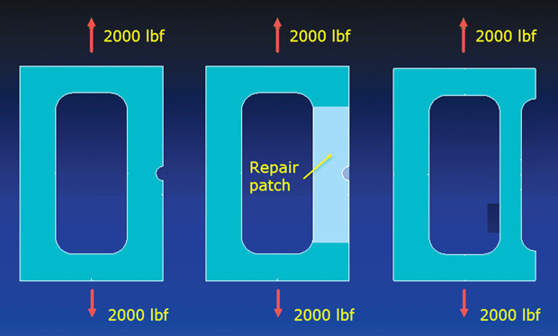 Figs. 1 to 3 (left to right): Original damage dressed to a notch shape; Repair scheme: doubler on right-hand leg; Repair scheme: flared right-hand leg.
A series of FEA models were run to investigate the two schemes. The doubler patch is the most intuitive repair, based on strength consideration. We are putting back the same thickness of material across the defective region. However, the net area in the section increases, which increases the stiffness. This in turn attracts more load. This effect is shown in Fig. 4, for a range of notch sizes. The doubler repair forces remain constant at 800 lbf in the undamaged (LHS) leg and 1200 lbf in the repaired (RHS) leg.
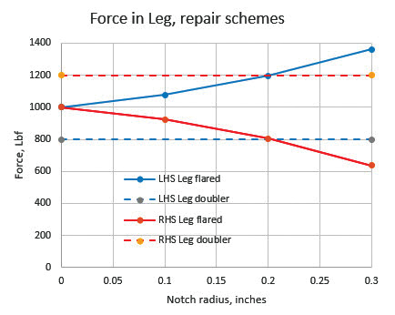 Fig. 4. Relative forces in each leg for the two repair schemes.
The flared repair scheme on the other hand, has a reduced area in the repaired (RHS) leg. The reduced stiffness is due to this, over an effective length. Hence, load increases in the undamaged (LHS) leg. This can be seen in Fig. 4 for a range of notch sizes. For zero notch, the legs are equal area. As the notch size increases the forces start to vary between the two legs. At a 0.3-in. notch, the forces vary as 1362/638 lbf.
The local stress concentrations around the notch, under the repair doubler patch are negligible, as shown in Fig. 5. The LHS and RHS legs have the same stress values, at 1600 psi. The reduced force attracted to the RHS leg (stiffness effect) is offset by the reduced cross section area (strength effect).
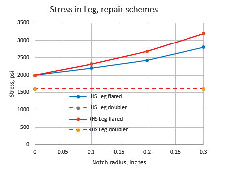 Fig. 5: Relative peak stresses in each leg for the two repair schemes.
The flared repair scheme has less overall cross sectional area than the doubler scheme. The datum zero notch stress for both legs is 2000 psi in the flared repair scheme. However, as the notch size increases two things are happening; the RHS flared leg is reducing in cross sectional area and attracting less load (stiffness). The reduced cross sectional area is increasing the stress (strength).
As the notch size increases, the net cross sectional area of both legs decreases, so both legs see an increase in stress. However, the stress distributions are virtually uniform across each.
It may well be possible with the example structure to have a successful repair scheme that works by reducing material, using a flared profile. This is perhaps counterintuitive and we would normally seek to add material to regain strength.
It can be useful in design to consider the influence of relative stiffness as a subtler way of changing load paths, rather than correcting strength directly by adding material.

Tony Abbey is a consultant analyst with his own company, FETraining. He also works as training manager for NAFEMS, responsible for developing and implementing training classes, including e-learning classes. Send e-mail about this article to [email protected].
Follow DE


About Us · Contact Us · Editorial Team · Advertising · Privacy Policy · Subscriber Services · © 2026 Digital Engineering 24/7 · Peerless Media