Helping design and engineering professionals discover, evaluate and specify technologies and processes that shorten the design cycle and enable success.
Alert!
Digital Engineering ceased publication on July 1, 2026. This website remains available as an archive of engineering content.
For inquiries or information, please email [email protected].

May 2026 Special Focus: Artificial Intelligence in Design and Simulation
In this Special Focus Issue, learn about the latest developments in the integration of artificial intelligence into engineering workflows.

Design & Simulation Software Guide 2025
In this Special Issue, Digital Engineering presents its second annual guide to design and simulation software vendors.
 In my February column, I explained the background to topology optimization. The piece prompted discussion via various social media, including requests to clarify the differences between topology, topography and topometry optimization.
I will explain in this article what the different methods do. However, it is difficult to distinguish between the terms based on normal language usage. Being an engineer, I like to know where things come from, as well as how and why they work.
I had no clear idea what the three terms meant in general usage, other than we talk of topology in the context of maps and FEA (finite element analysis) meshes. Topography also has something to do with maps doesn’t it? As I write this, my spellcheck is happy with the first two, but topometry? Forget it!
The earliest clear definition I can find is a learned paper1 written in 1912 by an American geologist defining these new French terms. He takes six pages to explain that it is a classification that better defines professional standing. The pure science of landforms and shapes is topology. When considering usage in a trade such as map making, it is called topography. When used for creating just local maps, it is called topometry.
So how does that help us? Well I would suggest the following as a memory aid:
• Topology is the general 2D or 3D big picture. As explained in the previous column, it uses 3D or 2D space to define an efficient distribution of material that takes load paths from application region to reaction region.
• Topography is a 2D shell height mapping that can push elements out from a nominal surface to form beads or swages to increase bending stiffness and strength.
• Topometry is a 2D shell thickness mapping, which allows a free form distribution of thickness in a surface to vary stiffness and strength. It was generally known as free sizing optimization and the idea has been around for a long time. My company, BAC, was using this approach in the 1970s to evaluate wing skin thickness distribution. I believe the term was first used commercially around 2000 in the GENESIS product.
I have asked some of the key developers in this area for the reasoning behind the terminology. Nobody is quite sure where topometry came from!
Let’s look more closely at topography and topometry.
Topography relies on offsetting shells from their original datum plane as shown in Fig. 1. A line of shell elements has been offset from the datum plane to increase bending stiffness. The user can define:
• The maximum height of the element offset.
• Whether it is a normal or local direction.
• The width of a typical bead or swage that will be formed (which controls the grouping of offset elements).
• Active or inactive regions.
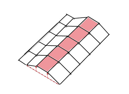 Fig. 1: Line of shell elements offset from datum plane to form a bead.
The method is a variant of classical element shape optimization. The nodal degrees of freedom (DOF), which define the design variables in shape optimization, are controlled by definition of the above input parameters. This is a neat way of overcoming one of the difficulties of shape optimization: How to control potentially hundreds of thousands of independent degrees of freedom nodal directions. Any of the formal optimization definitions for constraints or objective function can be applied to any response (stress, displacement, frequency, mass, etc.). This means that potential configurations that evolve using this technique can be rigorously checked, unlike topology optimization. However, it is very likely that the particular distribution of stiffening beads or swages will be too organic and will need some tidying up to create a manufacturable component. A subsequent check will be needed on this cleaned up configuration. However, it usually does not drift too much from the original optimum.
This is a variant on traditional size optimization and operates on shell thickness. A zone of shell elements is defined that allows free-form variation in shell thickness. At its simplest, the method allows each shell thickness to be an independent design variable. This is free to adopt a thickness between upper and lower limits. The resulting distribution of thicknesses is almost certainly not manufacturable. That does not matter. It is the idea of the overall configuration suggested by the thickness distribution that is important. However, the configuration will be rigorous, obeying whatever constraints we apply. The solution drives toward minimizing or maximizing a true objective function. It is up to us as engineers to decide what guidance we can derive from this in our search for a real design. The response you’d have gotten in the ’70s from hard-bitten Lancashire aircraft designers was: “Daft lad, get a real job!”
I think the role of conceptual configuration design tools is more widely accepted today.
Each of these three techniques allows exploration of design configurations suggested by the optimization solution. All three can give very radical results, and each uses a different approach to the solution. Topology is truly the wild child. As described previously, it can provide very creative designs that have to be tamed after mapping to real designs and checking actual strength, stiffness, etc.
Topography is limited to 2D shells and can be controlled more. It may give hints on bead or swage configuration, which are close to something we could actually make. Strength, stiffness and other criteria can be more closely monitored. It is more rigorous from an optimization perspective.
Topometry is also limited to 2D shells and is rigorous — but is another conceptual tool. Its purpose is to suggest distributions of thickness to give most efficient designs. The method is also described as free form optimization, which is really a better description.
In summary, all three “topos” are here to stay — particularly with application to additive manufacturing. Today it is generally understood these are tools to explore creative new ideas — no longer the daydreams of a daft lad.
References
1. Topology, Topography and Topometry. Francois E. Matthes. Proc. American Geological Society (1912).

Tony Abbey is a consultant analyst with his own company, FETraining. He also works as training manager for NAFEMS, responsible for developing and implementing training classes, including e-learning classes. Send e-mail about this article to [email protected].
Follow DE


About Us · Contact Us · Editorial Team · Advertising · Privacy Policy · Subscriber Services · © 2026 Digital Engineering 24/7 · Peerless Media