
A stereolithography machine with parts being printed. Image courtesy of Proto Labs.


Latest News
December 1, 2017
3D printing has opened up new flexibility and possibilities when it comes to design for additive manufacturing (AM). Engineers can create complex shapes and combine multiple parts into one in ways that were not cost-effective to produce using traditional machining or injection molding.
But that complexity comes at a cost, and many early adopters experienced the pain of failed builds, expenses and out-of-spec parts because they did not fully grasp the requirements and limitations of the support structures, new materials and post-processing steps needed to bring those designs to life. Traditional CAD design practices and simulation processes have also proven challenging to migrate into the 3D printing world.
Design for additive manufacturing (DfAM) requires a new way of looking at parts—redesigning them for print operations rather than adapting existing drawings. Common features like horizontal circular holes raise new design considerations, even as AM processes may reduce complexity in other areas.
Designing for specific manufacturing methods isn’t anything designers don’t already face—if a part is going to be milled, you have to consider the tool path; injection molding requires thinking about draft angles. 3D printing requires learning a new set of limitations and requirements, while also adopting a new mindset when it comes to taking advantage of the benefits of the technology.
“What we’ve found with 3D printing is really that a lack of education causes these roadblocks,” says Ben Redwood, director of supply chain at 3D Hubs and co-author of “The 3D Printing Handbook.”
“People are aware that there are limitations, but they don’t know what they are,” Redwood adds.
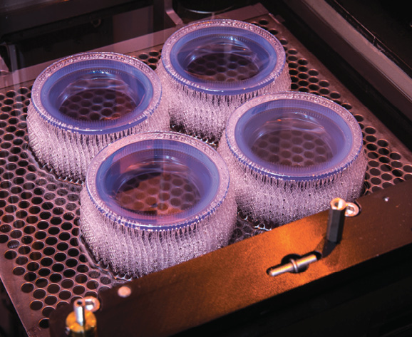 A stereolithography machine with parts being printed. Image courtesy of Proto Labs.
Those limitations and possibilities can vary significantly depending on what type of printing process you are using. In the book, Redwood and co-authors Brian Garrett and Filemon Schöffer outline the differences in support structure requirements, finish quality, post-processing and other elements for the major 3D printing technologies. Each one has strengths and weaknesses depending on the part type and application.
Starting from Scratch
“Engineers are looking at redesigning parts in an entirely new way,” says Tod Parrella, senior product manager for NX Design solutions at Siemens PLM Software. Siemens’ own gas turbine division was able to consolidate more than a dozen components in a burner assembly into a single design using additive manufacturing, but “the possibilities opened up using additive in the actual design of parts aren’t free by a long shot,” Parrella adds. “There is a whole new set of design constraints that needs to be considered.”
Those constraints are numerous, but some of the most common elements that can lead to a failed build or add expense or time to the process include:
Layer Height: For processes where material is deposited in uniform layers, the height of layers affects build time and finish quality. Generally speaking, the thicker the layer, the faster the print, but the rougher the finish.
Wall Thickness: This can be a challenge for companies trying to migrate an existing design that was previously injection molded or machined to a 3D printing process. “People will try to create extremely thin or thick geometries based on conventional methods,” says Allen Kreemer, senior manager of applications engineering at Stratasys.
Very thin walls won’t survive the print process, while very thick structures will result in slow builds and higher costs. “Don’t print a brick,” Kreemer says. “It’s inefficient and expensive. You want to hollow out or use a honeycomb fill for a thicker geometry, and even that still requires a large volume of material that may be cost-prohibitive.”
Wall thickness also affects material curing rates (with some processes) and part performance. “If you design a hinge or a snap fit, the wall thicknesses around those features are going to affect how the part works,” says Jon Eric Van Roekel, process engineering manager for 3D printing at Proto Labs.
Shrinkage/Warping: Again, this can vary based on the material and printing process. As the material cools during the build, different features can warp or shrink, which causes cracking. Consistent wall thicknesses can help avoid this, as can part orientation on the print bed.
Supports: Holes, overhangs, edges and other surfaces may require support structures during the build process that have to be removed in post-processing. Removal of the supports can affect the final finish quality. In addition, a design that requires too many supports can result in large amounts of expensive scrap material and slower build times.
For some processes, water-soluble supports can be easily washed away in post-processing. Others require time-consuming machining or sanding.
Designers can reduce the need for supports by avoiding sharp overhangs and angles. “You can design around self-supporting angles so you don’t need the supports running up the side of the part,” Kreemer says. “That also improves build speeds and reduces cost, as well as shortens post-processing time.”
Orientation: The orientation of the part in the print bed can have a significant effect on build times, the need for supports and even the strength of the final product. In Fused Deposition Modeling (FDM) and other processes, the layering of the material during printing can affect part strength. Parts under tension should be printed with the build direction parallel to the load.
Orientation is an important topic designers should discuss with the manufacturing team. “It’s often a surprise to customers because it can jack up the lead times and time-to-part, and also significantly affect the part price,” Van Roekel says.
Variability: With the exception of expensive, high-end production systems, 3D printing still generates a lot of variability in quality. The same machine can give you different results depending on the time of day, the operator or the age of the material being used.
Many AM systems can require a significant amount of maintenance and calibration to ensure part consistency. “AM is not nearly as stable as injection molding,” Van Roekel says. “We’ve seen in the past a lot of variability and dimensionality, as well as differences in surface clarity of parts. We put a lot of effort into maintenance and tracking all of the compensation values so we can reduce the amount of variance both machine to machine, and build to build.”
Holes: There are two types of challenges when it comes to holes. First, some print processes (like those using powder) require escape holes so that excess material can be evacuated during or after the build.
The holes can be plugged or filled after printing if they affect the performance of appearance of the part. “Putting holes all over a design doesn’t always appeal to people, but once we explain the risk of the print failing, they are usually open to it,” Redwood says. “There are solutions, such as plugging the holes and sanding them. Quality is really the main driver.”
Holes that are part of the actual design present different challenges. To print a circular, horizontal hole requires a significant amount of support material. Luckily, in the 3D printing world, holes no longer have to be circular.
“Over the years, we’ve found that no matter how perfectly the machine can print, never trust a round hole to come off that machine, regardless of part orientation,” Kreemer says. “Every operator winds up reaming out the holes using conventional methods.”
Because of this, Kreemer says that with FDM machines, Stratasys recommends designing undersized square holes that are rotated 45°. “If you make a hole round, the software is going to generate a support inside that hole, which slows you down and wastes material. If you convert that to a square and rotate it, the software ignores it and doesn’t add a support. Once the build is done, that square hole is a perfect center point for the drill to ream out the hole after the fact.”
Companies that are new to additive must realize that using additive versus machining or injection molding is not always an either/or proposition. Metal parts may need to be machined to obtain the correct surface finish, for example, or holes may need to be widened or drilled after the fact. The design may also need adjusted to accommodate those post-processing operations.
“That’s another area where engineers are going to have to think about these issues, and learn to go through an iterative process to modify the design so they get a final part that meets their requirements,” says Bob Yancey, director of manufacturing and production industry strategy and business development at Autodesk. “Having more intelligence in the design tools to guide them upfront so they can go through fewer physical iterations is going to be important.”
Software Evolution
However, modifying designs so that they are optimized for AM is still a process that often happens later rather than sooner.
“One of the impediments is that CAD software generally being used in industry was designed for traditional manufacturing processes,” Yancey says. “Being able to represent some complex geometries can bog down a CAD system. There is also a lack of understanding and experience within the design community in how to design for additive and take advantage of some of the unique capabilities it presents, as well as address its limitations and constraints.”
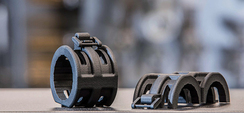 A multi-jet fusion part. Image courtesy of Proto Labs.
Siemens has implemented a suite of design validation and checking capabilities to help ensure designs are optimized for manufacturing. “We are taking those tools and extending them to consider design for additive,” Parrella says. “We have tools that can run those checks very quickly and show where the manufacturing engineers are going to build supports based on the orientation of the part.”
That opens up a dialogue between the design and manufacturing engineers, because the design or the orientation can be changed to alter the location of supports, or reduce the need for them by creating features that are self-supporting.
There are also services like 3D Hubs where designers can upload a file and do a quick analysis on which technology is most suitable for the application, or where designer features might need altered for additive.
That level of automation and intuitive software interaction doesn’t exist on a wide scale yet. “We’d love to be there at the beginning of the drawing stage,” says Stratasys’ Kreemer. “We’re really at the mid-mark now with tools that can alter a current design. If you can import a design and apply all of these rules in an automated setting, that will be a huge leap. That’s where the industry needs to go. There’s also room for more software partnerships and even acquisitions to make this seamless.”
Simulation is also an evolving area when it comes to additive, because the build process itself has to be worked into the simulation—and the existing knowledge base relative to materials and other elements is still emerging. “A good example is heat buildup when using fused metal deposition,” Parrella says. “Heat buildup in the part is going to cause all sorts of challenges with how the final part shape ends up. Support structures can remove heat from the build process and affect part warping.”
There is also much greater reliance on materials and processes when it comes to qualifying parts for stringent applications like aerospace and automotive. Manufacturers will need to validate their entire additive manufacturing process to ensure part quality—and that includes how materials were sourced, handled and stored.
That’s going to be difficult in some cases because the material data is still being created, and new types of structures will require additional analysis. “It’s very difficult and time-consuming to get good simulation and correlation because we just don’t have consistent XYZ properties,” Kreemer says. “And we’re still not able to simulate around a failure—occlusion or voids in a build.”
Lattice structures are a good example, Yancey says. “There’s not been a good way to simulate those types of structures,” he says. “The research is going on, but there’s no successful strategy for simulating lattice yet.”
Generative design approaches will also be important—designers can specify variables, constraints and objectives, and then let the software generate design iterations that factor in those variables. “Our generative design approach can help come up with a range of solutions that an engineer can sort through and determine what type of geometry will best meet engineering and business needs,” Yancey says of Autodesk. “For AM, particularly in metals, that allows engineers to test designs before building them to make sure they won’t have issues with residual stresses or distortions.”
Other advancements like topology optimization will also help improve the simulation of the entire process. “You upload the part in a large, bulky shape and then add loads and parameters to simulate the environment,” Redwood says. “You can design for uniform wall thickness, or ways to dissipate heat. That opens up the door for more repeatability.”
Design for Additive Manufacturing Requires a New Mindset
The adoption of 3D printing for manufacturing will require enterprise-level disruption and a new approach to product development. It will also require a lot of research and experimentation, as well as ongoing design for additive manufacturing education.
Yancey says that many companies with AM groups have turned to younger engineers who aren’t biased by their experiences with traditional manufacturing processes. “There is a lot of retraining that needs to happen with existing design engineers, and we have to develop curriculums in our schools that can train them for additive manufacturing. The bulk of current curriculums are really built around traditional approaches.”
Manufacturers also have to make the leap to designing specifically for AM. “The worst case is to try and print a molded part,” Kreemer says. “If they only issue one set of drawings around injection molding, it’s not going to work. But they aren’t willing to invest in redesigning for additive. Companies will need to make a bold move and say, ‘This part will only be printed for the life of the product,’ so they aren’t doubling the design time.”
Not every part or assembly is going to be a good candidate for AM, or may require multiprocess manufacturing that combines printing with machining or other approaches. Companies will need to balance additive’s ability to reduce part complexity, weight and or cost against the inherent complexities that come with 3D printing.
“When people come fresh to the technology, they do think that anything is possible, but that’s just not the case at the moment,” Redwood says. “You have to present the limitations and design requirements of the process, and adjust the design accordingly.”
Ultimately, more of these considerations will be part of an automated process much earlier in the design phase, whether through generative design approaches or analytic tools that can evaluate designs based on their compatibility with different AM processes.
There will also need to be more collaboration among manufacturing, design and R&D engineers. “That’s a big cultural shift,” Kreemer says. “We either have to move to a more well-connected R&D and production staff, or create more opportunities for production engineers to tinker and test new things. That’s difficult, because they just aren’t wired that way. Creating innovation centers can allow for that experimentation.”
Subscribe to our FREE magazine, FREE email newsletters or both!
Latest News
About the Author
Brian Albright is the editorial director of Digital Engineering. Contact him at [email protected].
Follow DE

