Helping design and engineering professionals discover, evaluate and specify technologies and processes that shorten the design cycle and enable success.
Alert!
Digital Engineering ceased publication on July 1, 2026. This website remains available as an archive of engineering content.
For inquiries or information, please email [email protected].

May 2026 Special Focus: Artificial Intelligence in Design and Simulation
In this Special Focus Issue, learn about the latest developments in the integration of artificial intelligence into engineering workflows.

Design & Simulation Software Guide 2025
In this Special Issue, Digital Engineering presents its second annual guide to design and simulation software vendors.
Mainstream finite element analysis (FEA) has a long tradition of using a discrete element-based approach. The elements define the structural domain, and their combined behavior describes the response.
A range of methods described as “meshless” is emerging. This is a paradigm shift for the traditional analyst, and there is much resistance. However, for those new to FEA, or those who feel bogged down with meshing, it may be a significant breakthrough.
Let’s look at what is meant by a meshless approach because a variety of methods carry that label. Is there a future for these methods in mainstream analysis?
I have been using traditional FEA methods since I started at British Aircraft Corporation (BAC) in Warton, Lancashire, England, in 1976. Then, FEA was new and restricted to large companies like BAC who could afford the expensive mainframe computers and software licenses. Some of my stress office colleagues seriously doubted the validity of FEA. Fortunately, FEA was considered a key technology by BAC, and they developed many pioneering techniques.
Since then, adoption of the method has been steady across many industries by a wide range of engineers and designers. It has taken a lot of development to reach the stage where, if used carefully, a reasonable structural analysis can be done.
Early element technologies and methodologies were sometimes found to be incorrect and engineers adopted more robust and reliable solutions. The NAFEMS organization, who partnered with DE to run the Conference on Advancing Analysis and Simulation in Engineering (CAASE) last year, played a key role in developing benchmarks to form a foundation for the FEA verification used by a range of software vendors.
Above, I included a caveat on careful use. Two essentials affecting meshing are:
1. Demonstrating a converged answer for stresses at key points within the FEA mesh. I have written about this in DE articles (January 2013, February 2014 and May 2017). It is one of the cornerstones of my Introduction to FEA training classes.
2. Checking element quality. I have written about this in several DE articles as well (see DE January 2014).
Traditional FEA relies on solving a complete component by breaking it down into simpler regions (i.e., elements). The displacement response of these elements is defined via internal shape functions. The shape functions are controlled by the nodal displacement responses at each degree of freedom (DOF) at the node.
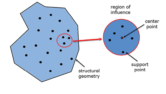
Fig. 2: Influence region within a structural domain.
The search for an overall solution for displacement throughout the component is a search for a minimum energy state. However, the strain, and hence stress, are not continuous across the component, so we can get the well-known stress “jumps” between adjacent elements. By using convergence and good shaped elements as goals, we can improve the stress response.
Now that the background and skill set of new users to FEA is much broader, the range of accessible FEA solution types is also larger. An increasing segment of users want FEA that is straightforward to use. The techniques that traditional FEA demand, particularly with respect to meshing, represent a steep learning curve.
I feel every sympathy for a designer using a CAD-embedded FEA program who wants to assess the approximate strength of a design as early as possible. In the broader context of loads, boundary conditions and modeling techniques, there really are no shortcuts. But the meshing burden is something that we have all inherited, and every analyst would be happy for it to quietly go away. An FEA mesh is just a means to an end. It shouldn’t dominate the FEA process. However, sloppy meshing can give bad results, and high-quality meshing usually requires skill and experience.
Can meshless technologies ease that burden and still give acceptable results?
The term “meshless technology” can be confusing. Within this broad definition, some technologies truly do away with conventional FEA elements, some use adaptive FEA elements and some use conventional FEA elements behind the scenes. A purist would argue that doing away with conventional elements is the true definition of meshless analysis, but I think it is more useful to think of meshless technology as delivering results where the accuracy level can be quantified, and the meshing burden is removed. I have used that approach in this article.
One technology that has been around for quite a while is the use of adaptive p-elements. Each element can develop its own required order (p value) of internal shape function. A single element can handle steep stress gradients. This contrasts with the more traditional h-element method, which requires an increasing number of elements to handle areas of steep stress gradient. This is the mesh convergence approach I described earlier.
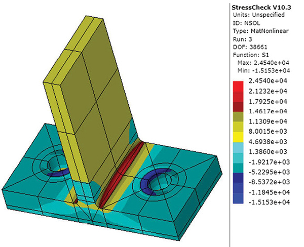
In the May 2018 edition of DE, I reviewed CAE Handbook from ESRD, which uses the StressCheck solver. It provides automatic stress convergence by running a series of analyses. The p value of the elements adapts until a target convergence criterion is met. The convergence history is plotted by default. Fig. 1 shows the mesh required in the bracket example I ran in the review.
The mesh requirement in Fig. 1 is clearly a lot simpler then a traditional h-element FEA mesh. This mesh has been prepared by ESRD experts and is a templated example from their Handbook library. This represents the best scenario for a casual FEA user. The focus is on the engineering, rather than the meshing.
The aircraft industry is an example where this fits well: A wide range of standardized brackets and fittings are used, which can be templated for subsequent analysis by less skilled users. However, meshing an arbitrary geometry still needs some experience and care to get good answers. For those with that experience, the reduction in the meshing burden is attractive. Though this creates a paradox for CAD-based designers who do not have a strong FEA background: The template approach gives a well-controlled environment, but what happens if a radically new design is required?
This means there are two types of users, those checking strength of the component to a formal requirement and those wanting to get a feel for the strength of the component as the design is evolving. The rest of the article really focuses more on the latter area.
I wrote a previous DE article on preparing analysis for redesign (November 2017). I used an electronics chassis, and assessed it for preliminary strength and stiffness, subject to many design changes associated with electronics and cooling equipment positioning.
The CAD geometry can be meshed directly with solid elements. It can be made to optimize the mesh and be able to handle the loads and boundary conditions. Redesign requires remeshing, and this becomes a significant and unwanted burden.
Idealization can also be used to create a shell and beam mesh model. The motivation is that many potential design changes can be analyzed by varying wall thicknesses and beam dimensions directly. The downside is that 2D and 1D idealization is not a straightforward process within a CAD environment and some skill and experience is required.
One objective of meshless technology is to overcome these issues by allowing a tighter integration between new design concepts and their structural response assessment. The latter could be strength, stiffness or fatigue life, etc. In preparing for the article, I did background theory research. I also talked to two FEA software companies who have introduced products to address the design dilemma by using meshless technology. They present an interesting comparison in approach. As ever, my stance is completely neutral, and I very much thank the product managers and developers who have assisted me.
One approach to meshless technology is to move completely away from the normal FEA discretization. As a reminder, the FEA approach divides the geometry into the familiar elements, and then defines the displacement response within each element via shape functions. In the Element Free Galerkin (EFG) method, the geometry space is instead filled with points, which are initially randomly distributed. Each point, in turn, becomes the center of a local region of influence. Other points are found within the region of influence, and they define the basis for a set of shape functions to be created on the fly. Fig. 2 shows a simple schematic of this.
The geometry is filled with regions of influence, in some variations a simple mesh is used to map the points and for post-processing. The regions can overlap, and they can also be discontinuous, for example, to represent a crack in fracture mechanics. The overall structural energy minimization equation is created by assembling these general regions of influence. A Galerkin energy minimization is used, hence the name of the method.
The internal displacement field is the unknown to be solved, as in traditional FEA. However, the boundary conditions—zero displacements at boundary nodes—are imposed on the problem via a penalty solution. In traditional FEA these are set as a hard zero; with the EFG method, they will initially not be zero. There will be a series of solutions that iterate toward a condition where boundary displacements approach zero, and corresponding reaction forces converge.
Demonstrating reaction convergence also demonstrates convergence of the method. It is possible to map a continuous strain field throughout the structural region, which then gives rise to a corresponding continuous stress field. This is a simplistic description of the process.
For a designer, the attraction is that there is no requirement to prepare mesh for the geometry. There are wider potential advantages for the method. These include lack of element mesh bias on responses, the ability to withstand high structural distortion without corresponding element distortion, and splitting or deletion of arbitrarily regions corresponding to crack growth or damage areas.
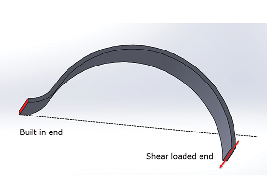
Fig. 3: Raasch hook. Image courtesy of SIMSOLID.
There are a range of meshless techniques similar to the EFG method. The field is expanding and there is much literature—try researching it, but beware that the math quickly gets overwhelming!
I talked to cofounders Ken Welch and Victor Apanovitch at SIMSOLID (now acquired by Altair) and was given a demonstration of the SIMSOLID product. With it, users can analyze very large assemblies in real time. Design changes were created with the coupled Onshape CAD tool and re-analyzed with the same fast turnaround. Exploring the strength, stiffness and load path implications of an evolving design becomes intuitive.
This product has a true meshless approach, generally along the lines I’ve described, although the exact technology is proprietary and not necessarily the EFG method. The SIMSOLID DOF are described on their website as being functionals with geometrical support in the form of volumes areas, line clouds and point clouds. The solution is always an adaptive one. More sophisticated and denser distributions of DOFs are generated at each iteration, based on the stress distribution evaluated. Overall convergence is demonstrated by converged reaction forces.
The geometry is internally interrogated and classified. For example, a distinction is made between potato-like geometry and thin, shell-like regions or components. This controls the distribution of DOF within each of these regions. I was particularly interested in the thin shell geometry representation. This is one of the most difficult idealization and meshing areas in traditional CAD-embedded FEA, where dedicated thin shell elements are used.
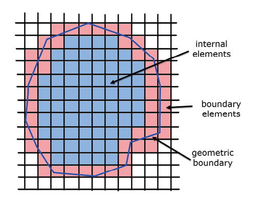
Fig. 4: The principle of volumetric meshing.
SIMSOLID maps the original geometry in a 3D sense and there is no conversion to a 2D idealization. Their verification documentation contains a benchmark called the Raasch hook, shown in Fig. 3.
This consists of a strip that is bent into an “S” shape. It is fixed at one end and loaded vertically at the other end. This generates a complex distribution of axial, bending and torsional stresses. When first introduced, many existing thin shell elements gave poor deflection and stress results. As a result, FEA shell element technology improved. That SIMSOLID can handle this configuration is reassuring.
Welch and Apanovitch emphasized that SIMSOLID is aimed at design community users who want fast answers to configuration changes, both within a part and within the overall assembly. The objective is not to achieve high levels of stress accuracy, as this would require a formal stress check. The user is encouraged to think of design and analysis of complete assemblies, rather than individual parts. Meshless technology enables this in three key areas:
1. the meshing burden is removed;
2. meshless technology enables very fast analysis; and
3. the geometry classification includes automatic contact region detection, and can intelligently define bolts, seam welds and other components on the fly.
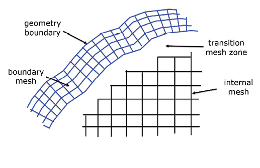
Fig. 5: Schematic of the element skinning method.
One interesting aspect is the emphasis on the reaction forces to ground and within parts, due to contact. A free body diagram of each part is always available—great for load path assessment and potential global local modeling. The concept design can be migrated into Altair’s FEA products for a full assessment.
I am planning to do a full walk-through of SIMSOLID in a future article. I have not done it justice in this brief description.
Volumetric meshing is based on the principle of having a very regular mesh in the interior of a geometric region and then concentrating on adapting the mesh around the boundary surface. A schematic of the idea is shown in Fig. 4.
The technique is used heavily in the computational fluid dynamics (CFD) world, where there are a tremendous number of variations on the technique.
Because the interior mesh is not controlled by the boundary, it can be optimized for meshing speed and efficiency. The element count stays relatively low, giving big performance advantages. The boundary elements are then refined or adapted in some way.
One method remeshes the boundary region locally, giving a conforming faceted surface. An alternative is to produce a skin of high quality elements that then transitions to a regular mesh. Fig. 5 shows a schematic of this method.
Another approach is to interpret the edge mesh region as a functional fit. This is analogous to topology optimization where the moving material boundary is defined by a smoothed material density and stiffness gradient through the fixed mesh. The stress distribution is interpolated through this “virtual” region. Fig. 6 shows a schematic of this type of method.
In Fig. 6, the density varies from the full parent material in the interior shown in the dark color, through to external boundary, indicated by the lighter colors. The method provides an approximation of the stresses at the boundary smoothed through a fixed mesh.
As with the true meshless methods, there are many variations on this theme. Additions not covered include polyhedral meshing, which can fit elements of adapting high-order geometric shapes to the external boundary and to the interior.
I also talked to Justin Hendrickson, product manager for ANSYS Discovery Live. The product uses meshless technology and is aimed at users exploring conceptual designs. The approach used in Discovery Live is volumetric meshing. As before, this is proprietary technology and goes beyond the simple descriptions I have given.
Justin emphasized the roadblocks that traditional FEA presents within the design community:
Hendrickson gave me a demonstration of the product. With ANSYS Discovery Live, the geometry environment is provided by ANSYS SpaceClaim. The other key technology, in addition to meshless FEA, is the use of NVIDIA graphical processing units (GPU) to provide very fast analysis time for models with very large numbers of elements (a typical model used in the demonstration had 15 million elements). The result of this is that analysis is continuously available, and any design change is automatically reflected in a new analysis. One loses the concept of an analysis “run,” and it is more of a continuous flow of updated stress and displacement results. This becomes a very immersive experience and provides immediate and intuitive feedback on design changes.
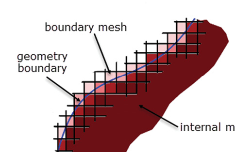
Fig. 6: Schematic of a material interpolation approach.
The user can control the fidelity of the underlying mesh. At the coarse setting, the model is giving a representation of the load path, but local surface details are approximate. Increasing the setting improves the geometry fit, the number of elements and the accuracy of the result. The surface fitting technique, typical of the volumetric modeling approach, is evident. Early layout work can use the coarse setting and then as details are refined, the fine setting. Hendrickson estimated that with this setting, an accuracy of 10%–20% would be a typical target. This is enough to get the design moving along the right lines.
There is then a migration path for users to put a design into the ANSYS traditional FEA tools for formal checkout.
Other physics are also available within this environment, including CFD and thermal analysis. These are also immediate interactions.
I plan to write a more complete article on ANSYS Discovery Live. Again, I have done the product scant justice with this quick overview, within the context of meshless FEA.
This article covers three approaches to meshless FEA. The p-element method, as embodied by ESRD StressCheck, simplifies the meshing task and provides fast analysis. This is a great approach for analysts. For designers, the templating approach using the CAE Handbook is attractive if working within known design variations.
On the other hand, for working up concept designs, the SIMSOLID and ANSYS Discovery Live products both provide intuitive environments that will allow designers to assess preliminary strength, stiffness and other responses. The “acceptable results” label is limited to this level. Both products target this arena and both teams emphasized that formal FEA can follow later, if required.
This emphasis on the level of accuracy, and subsequent product positioning, should reassure many traditional analysts. However, I look forward to the technology maturing in a similar way to traditional FEA with increasing accuracy and applicability. Then perhaps my meshing nightmares will be over!
Editor’s Note: Tony Abbey teaches both live and e-learning classes for NAFEMS. He provides FEA consulting and mentoring. Contact [email protected] for details.

Tony Abbey is a consultant analyst with his own company, FETraining. He also works as training manager for NAFEMS, responsible for developing and implementing training classes, including e-learning classes. Send e-mail about this article to [email protected].
Follow DEJoin over 90,000 engineering professionals who get fresh engineering news as soon as it is published.


About Us · Contact Us · Editorial Team · Advertising · Privacy Policy · Subscriber Services · © 2026 Digital Engineering 24/7 · Peerless Media