Helping design and engineering professionals discover, evaluate and specify technologies and processes that shorten the design cycle and enable success.
Alert!
Digital Engineering ceased publication on July 1, 2026. This website remains available as an archive of engineering content.
For inquiries or information, please email [email protected].


May 2026 Special Focus: Artificial Intelligence in Design and Simulation
In this Special Focus Issue, learn about the latest developments in the integration of artificial intelligence into engineering workflows.

Design & Simulation Software Guide 2025
In this Special Issue, Digital Engineering presents its second annual guide to design and simulation software vendors.
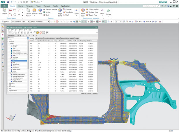 The weight of each defined layer of a composite is identified for a vehicle’s “B” pillar design, specified with Siemens Fibersim software, for a model analyzed with Siemens NX 10 software. Image courtesy of Siemens PLM Software.
Product optimization begins in the design process but doesn’t stop with geometry: Material choices and manufacturing options are increasingly critical trade-off parameters. In addition, an optimization process should account for the manufacturing approach (mill, cast, stamp, layer) and possible subsystem assembly options (weld, rivet, glue). Making wiser decisions before a part or assembly is ever handed over for refined structural analysis is key to producing improved designs. Check out these recent and upcoming improvements in simulation tools that do just that.
Major players in both the CAD and CAE worlds have been tackling this faster/better challenge from various directions. “I see a very large focus on both geometry and materials together,” says Doug Neill, vice president of Product Development at MSC Software, “and both have challenges in the current engineering workflow. Technology is out there that helps, but nobody yet has the perfect push-button solution -- including us -- that makes it trivially simple to do lightweighting quickly and easily.”
Neill breaks down typical lightweighting approaches into three categories: Changing geometry to replace an existing component with a lighter one; using 3D printing to produce a more efficient structure; and specifying a different material that may not itself be lighter but is stronger, so less is needed.MSC Nastran and MSC Nastran Desktop Structures both support topology optimization for exploring design options. Neill says such topology software will tell users the most efficient place to put material, but he adds: “It’s a proposal, and it doesn’t say that the result will satisfy buckling criteria, non-linear contacts, failure mechanisms and even sometimes static strength.”
On the other hand, he explains: “Shape optimization has the ability to take more geometric concepts like parametric CAD and represent changes in those parameters in finite elements and do shape changes.” Neill says a third company offering, MSC Apex, represents current corporate philosophy: Geometry is great, but it needs to be in a CAE tool. Rather than trying to put physics into a CAD package, MSC Software is putting geometry, topology optimization and shape optimization into a CAE package.
Neill’s last observation is that currently, people doing topology optimization are almost always looking to replace metallic, homogeneous isotropic materials with inhomogeneous, anisotropic materials including those created by layered (additive) manufacturing. A real solution for that type of optimization is not yet available in one environment, though MSC Digimat software addresses the angle of composite material simulation.
Similar thoughts are echoed at Siemens PLM Software, where Edward Bernardon, vice president for Strategic Automotive Initiatives, agrees that optimization is not just about geometry. He gives the example of car companies needing to reduce frame weight for better fuel economy: “The packaging/styling guy says ‘this is the shape I have to have more or less (say, for a four-seater). I’m going to give you X dollars per pound to reduce the weight of this car. You can use steel, composites, magnesium, aluminum; you can glue it, rivet it, weld it, whatever you want.’
“So,” Bernardon explains, “the choice the engineer has to make is, ‘what material do I put where, and what’s the shape that achieves the stiffness I want?’ You need this information at a high level and at a detailed level.
“Ideally, you’d love to have tradeoffs of cost against the material you use, where you put cut lines, and how you join them, all in one place,” he continues. “This could be the CAD system, which allows you to trade off packaging, cost, manufacturability and the input you get from the analysis tools, such as strength. But you need it for composites, steel, magnesium casting, etc. There’s no software that (currently) solves this problem -- not ours, nor anybody else’s. Some of these tools exist but they’re not really at the fingertips of the designer. A tool like that is maybe five or 10 years into the future.”
What Siemens PLM Software does offer are pieces of this tool, such as FiberSim for composite design and the NX CAD/CAE family for design, simulation and manufacturing. “We see the opportunity to take some of these workflows that traditionally have been in the analyst’s domain and make them available in a format that is consumable for designers. The only way to really make that happen is if you are working in the same environment that the designer does,” says Ravi Shankar, director of Simulation Marketing at Siemens PLM Software. He notes that NX offers that ability: the analyst can create a workflow that designers can execute in their own environment, or the designer can start to do some CAE work to get some up-front feedback on their design.
Especially in the automotive and aerospace industries, ANSYS users have also been working for decades to reduce part weight. “There are two things to do: Optimize all components for light[er] weight and use a different material like a composite,” says Sandeep Sovani, global automotive director, ANSYS.
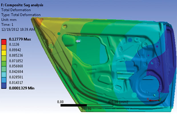 Vehicle door-panel design defined for composites, using ANSYS Mechanical and ANSYS Composite Prepost software. Design improvements for lightweighting are simplified with stack-up and lamination layout capabilities. Images courtesy ANSYS.
To optimize components, Sovani says analysts have traditionally used FEA (finite element analysis) and CFD (computational fluid dynamics) tools, including the individual multiphysics solvers within the ANSYS Workbench platform. In 2015, the company added ANSYS Integrated Multiphysics (AIM) to Workbench, offering a simulation environment designed for engineers of all skill levels that includes templates, automated processes and an intuitive user interface.
Another ANSYS optimization product within Workbench is Genesis Topology for ANSYS Mechanical (GTAM), developed as a vertical customization in collaboration with Vanderplaats Research & Development (VR&D). “A lot of parts are over-designed simply because [otherwise] very complex geometry would be needed for creating components that are structured along stress lines. Topology optimization supports just that: With GTAM, the region to be optimized is identified and Genesis runs in the background. This workflow could have been done without the GTAM function, but it would have been more cumbersome,” notes Sovani.
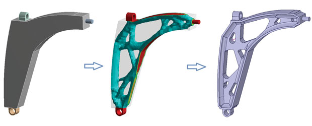 Optimal topology design of an automobile upper control-arm. The left part shows the initial design. The middle version shows the topology optimization results obtained with GENESIS Topology for ANSYS Mechanical (GTAM) from Vanderplaats Research & Development. The part on right shows the final CAD model cleaned up using ANSYS Space Claim. Image courtesy of Vanderplaats Research & Development.
Lightweighting through use of composites is also supported by ANSYS with its Composite PrePost software. This tool analyzes part performance when different composite stacking and orientations are considered. It is designed to work with ANSYS Mechanical but can write to other analysis packages, too.
Experts at COMSOL suggest three ways to optimize a mechanical design for lighter weight, offering something for all levels of engineer, notes Walter Frei, COMSOL application engineer. “The first would be for users already working with a CAD program such as SOLIDWORKS or Inventor for which we have a COMSOL LiveLink program,” he says. “For example, for pure structural analysis, you could use the core COMSOL Multiphysics package with a LiveLink product as well as the Optimization Module. You’d then tell the COMSOL software, these are the SOLIDWORKS, etc. dimensions (such as multiple hole radii) that can be changed, and pass those to the Optimizer. Say, ‘minimize the weight, constrain the stresses to not be above a certain value or keep the eigenvalues within a certain range.’ That’s the easiest to do.
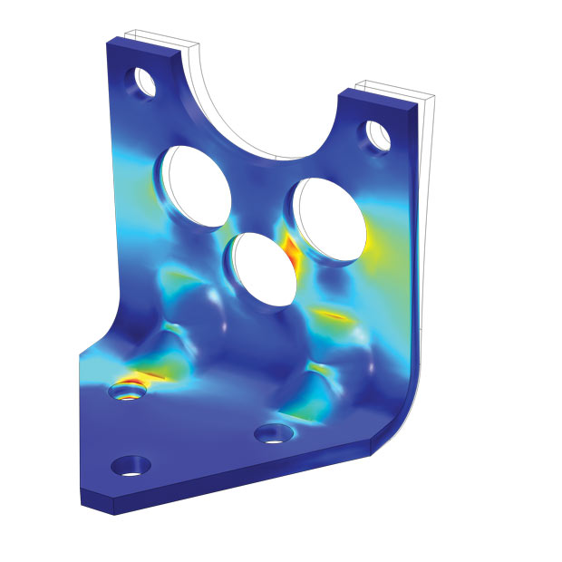 Shape optimization with COMSOL Multiphysics and its optimization module, where the weight of a mounting bracket is reduced. An upper bound is placed on the maximum stress allowed for the static load case, and a lower bound on the first natural frequency. Image courtesy of COMSOL.
“The second level up,” says Frei, “is shape optimization, which is little bit more involved.” He points out you can’t always just cut a hole in the part to remove weight; identifying a different cut-out shape (which could even be defined by a function) requires a geometry-deforming capability. “With this, the user has to put some thought into things ahead of time,” he says, “providing the optimizer some more inputs, but it gives you more flexibility.”
Not surprisingly, the third COMSOL option is topology optimization, where users don’t even start with a CAD model but rather with a “block” of specific material. Given certain constraints plus loads defined at several points, COMSOL software identifies where material could be removed. Frei notes that this is the approach that is generally used very early in the design process and can be very powerful.
Frei adds that you can absolutely optimize both geometry and material. “To COMSOL,” he notes, “there really is no difference between the two. Often the material is based on other constraints, such as monetary, that have nothing to do with lightweighting.”
Within the continually evolving Dassault Systèmes (DS) 3DEXPERIENCE portfolio, users of the SIMULIA product line can find a number of optimization functions moving up front and available to the designer. Over the years, acquisitions such as Isight for parameter optimization and Tosca for topology optimization, now brought into the 3DEXPERIENCE platform, show how much the company is expanding the value of simulation activities to tasks outside of the classic analyst group.
“We’re not trying to turn everyone into a simulation expert, and not everyone will be creating methods for topology. We want to make Abaqus and Tosca technology available in the right way: The designer is capable of describing the desired aspects -- ‘minimize the weight’ -- the analyst would fine-tune the resulting model, and vice versa,” says Dale Berry, senior director of SIMULIA Growth.
Michael Werner, formerly with Tosca and now a SIMULIA portfolio technical specialist, explains that optimization really helps build a bridge between the CAD and CAE communities. In the Tosca package, new features include optimizing structures with sheet-type geometry; methods for optimizing internal lattice structures for 3D printing are also in the works. He adds: “We’re developing targeted apps for both the designer and the analyst, and bringing Tosca closer to the Abaqus user base.”
The first 2016 subscription update of Autodesk Inventor addresses the goal of creating the lightest strongest part available. It employs a new technology called Shape Generator that uses shape topology optimization, and does so early in the process.
To lower part weight, “You could probably iteratively try a lot different things, but that’s just ‘whatever is in my mind, based on my experience,’ and oftentimes you get to a point where it’s good enough -- as light as I can get it,” says Derrek Cooper, director of Product Management at Autodesk. “This was the catalyst for Shape Generator: Instead of having the simulation folks doing optimizing in an isolated workflow, could we, in two or three clicks, help designers come up with the idealized shape?” He calls this conceptualized optimization, accelerating users to get to something that can be fine-tuned.
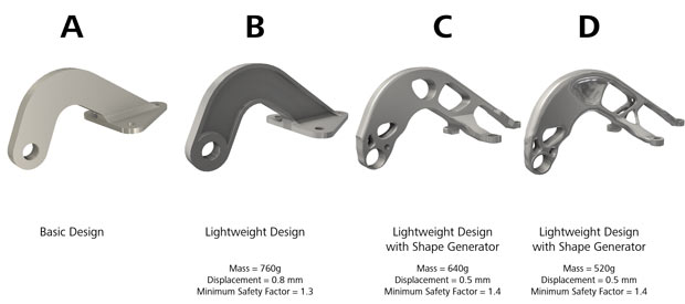 Four stages of lightweighting a bracket: simulation and analysis performed with the new Shape Generator feature in Autodesk Inventor. Users define part material, apply loads, identify fixed points and enter a value for the amount of mass to be removed. Image courtesy of Autodesk.
To invoke this Autodesk Inventor feature, designers specify material, maximum build volume (or general part shape), known contact points and all expected loads, then define a goal such as “reduce mass by 30%.” Clicking on “Generate Shape” then produces an STL file that could go right to a 3D printer, or into a CAD program for further geometry refinement. Cooper notes you can create a range of parts depending on the chosen material.
Creating structurally efficient designs up-front is also the main principle behind Inspire software from solidThinking, a wholly owned subsidiary of Altair. Dedicated to upfront (pre-CAD) design guidance, solidThinking’s Inspire generates a series of material layouts within a maximum allowable package space that will handle the required loads. “Traditionally the analyst would do a very detailed analysis and say to the designer, ‘I want a couple of changes’, then they go back and forth. There are a lot of communication gaps and frustration, so this is exactly what we’ve changed,” says Jaideep Bangal, senior application engineer at solidThinking.
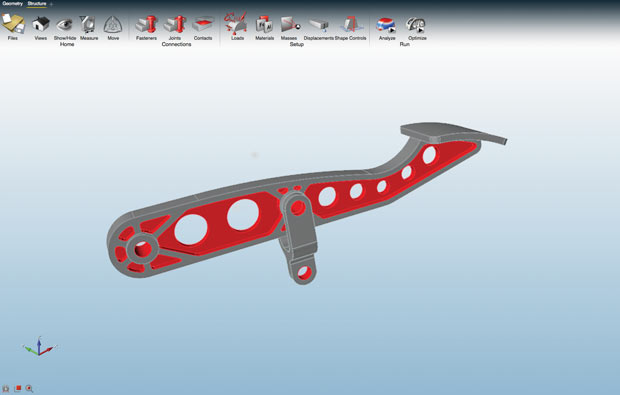
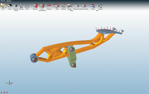
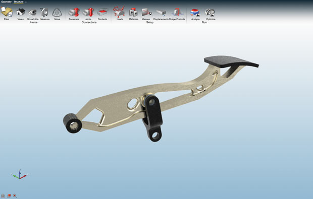 Lightweighting performed on a brake pedal: original design (top), design analyzed for load-bearing paths using solidThinking Inspire software (middle) and final CAD design of part refined for efficient manufacturing (bottom). Images courtesy of solidThinking.
The philosophy driving solidThinking is that design engineers should use the same kind of technology as the analyst to create a concept upfront that is structurally correct, using a solver that is mathematically correct but very easy to use. “This solver (in Inspire) doesn’t have all the knobs and tweaks as for the analyst,” says Bangal, “but it gets you to 99% of the goal. You don’t have to go back and forth (with an analyst), which means in an hour or so, you get many possible concepts.”
These concept models may display a very organic appearance, and are therefore presented as raw polygon forms that can be brought into any CAD tool and refined for manufacturability. Last year, Inspire added analysis and topology optimization tools that support assemblies such as fasteners, joints and contacts. New to Inspire 2016, users can perform buckling analysis, define dynamic loads (acceleration), set temperature values as a boundary condition, and specify sheet metal materials (a request by many automotive customers). Bangal adds that the next big thing will be evaluating and suggesting structures for alternative manufacturing possibilities like 3D printing.
More Info:

Pamela Waterman worked as Digital Engineering's contributing editor for two decades. Contact her via DE-Editors@ digitaleng.news.
Follow DEJoin over 90,000 engineering professionals who get fresh engineering news as soon as it is published.


About Us · Contact Us · Editorial Team · Advertising · Privacy Policy · Subscriber Services · © 2026 Digital Engineering 24/7 · Peerless Media