Helping design and engineering professionals discover, evaluate and specify technologies and processes that shorten the design cycle and enable success.
Alert!
Digital Engineering ceased publication on July 1, 2026. This website remains available as an archive of engineering content.
For inquiries or information, please email [email protected].


May 2026 Special Focus: Artificial Intelligence in Design and Simulation
In this Special Focus Issue, learn about the latest developments in the integration of artificial intelligence into engineering workflows.

April 2026 Special Focus Issue: Generative Design
In this Special Focus Issue, Digital Engineering takes a look at how generative design solutions can be used across different types of design problems and with a variety of manufacturing approaches to accelerate design space exploration, and…
Designers in the world of 3D printing/additive manufacturing (AM) will find a number of highly useful features among the hundreds announced in SOLIDWORKS 2018. In the Dassault Systemès SOLIDWORKS live webinar held on September 26, these tools were presented as new options for handling imported mesh files and optimizing designs to minimize mass.
Current SOLIDWORKS users have been able to import mesh geometry files, but had to convert them to surfaces to do any work with them. Such files often derive from scanned data, but may just as well come from a mesh file for a design that someone has shared, which you wish to modify without completely rebuilding it. In SOLIDWORKS 2018, you can bring in a number of mesh file formats and work with them directly – more like working with surfaces and solids.
“SOLIDWORKS 2018 introduces new ways to utilize mesh data, offering more possibilities than ever before for a variety of formats such as STL, OBJ and Additive Manufacturing files," says Craig Therrien, Senior Product Portfolio Manager, Dassault Systemès SOLIDWORKS. "First off, graphical mesh geometry now supports material textures and RealView appearances. Likewise, you can now perform sections on graphical mesh data as well. As a result, you can now better visualize and fully understand your mesh geometry right inside of SOLIDWORKS.”
Therrien points out: “We can do much more with mesh geometry, starting with the new Surface from Mesh Feature. This tool enables you to turn mesh data into SOLIDWORKS surfaces quickly utilizing a simple workflow. Just choose the type of surface you wish to create, then, using the purpose build Paint Selected Facets tool, you can easily swipe to select a handful of faces for the desired surface.”
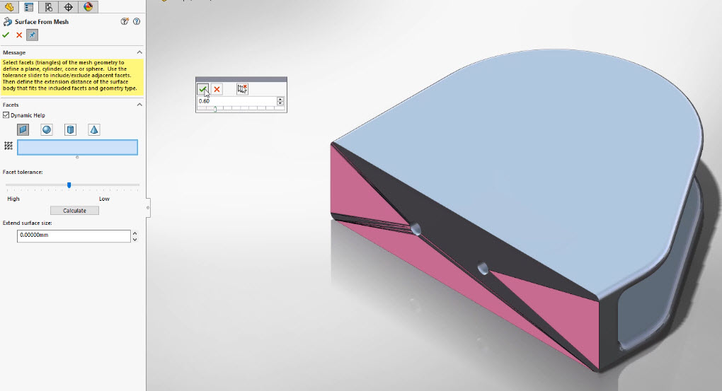 A mouse click in SOLIDWORKS 2018 converts mesh geometry into SOLIDWORKS surfaces, planes, spheres, cones and cylinders. (Image courtesy Dassault Systemès SOLIDWORKS)
A cool feature is that not every surface needs to be selected. Therrien goes on to say that simply by choosing Calculate, SOLIDWORKS will automatically gather the remaining faces for you, and create the appropriate surface. Once any number of surfaces has been created this way, users can work with all of the usual SOLIDWORKS Surfacing capabilities.
SOLIDWORKS 2018 also introduces the new Mesh Body type. Any graphical mesh can be converted into a Mesh Body directly from the right mouse menu. Mesh Bodies are similar to solid bodies in that they are water-tight, have mass properties associated with them, and can be sectioned normally, but Therrien says they do have some differences.
“You can take your mesh data much further with powerful new workflows specific to mesh geometry,” he explains. “For instance, you can add any geometry to mesh files using all of the familiar tools you’re used to in SOLIDWORKS. You can even reference the underlying mesh geometry when adding sketch relationships.”
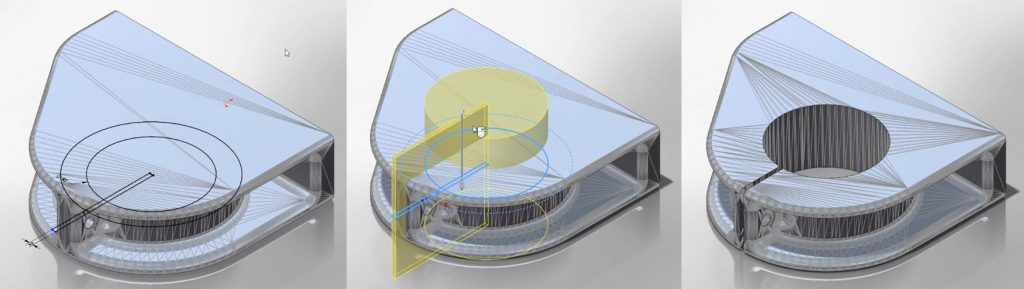 In SOLIDWORKS 2018, users can work directly with imported mesh files, turning mesh data into editable surfaces. (Image courtesy Dassault Systemès SOLIDWORKS)
The only difference, he adds, is these features aren’t automatically merged with the mesh geometry. To do that, you can take designs in the other direction, converting traditional solid bodies into Mesh Bodies. This ultimately allows you to take any geometry you’ve created and perform a variety of Boolean style features to further manipulate the mesh geometry.
The concept of lightweighting is driving many new designs, yet the resulting innovative and sometimes highly organic geometry may require AM technology for fabrication. In support of this growing field, SOLIDWORKS Simulation 2018 software now includes a new study type – the Topology Study. Therrien says the topology study capability enables designers and engineers to develop minimum mass components based upon linear static loads and restraints. The result from a topology study is a smoothened mesh file, which can be sent directly to a 3D printer for manufacturing.
When Therrien was asked about plans for further integration of design-for-AM features into SOLIDWORKS products, he replied, “The vast majority of 3D printer manufacturers are SOLIDWORKS customers and are also part of the SOLIDWORKS partner program. We regularly work with many of them to move additive forward and we have a lot in the works in this area, including (companies such as) Carbon, Desktop Metal, MarkForged, 3D Systems, Ultimaker, Formlabs and Stratasys.”

Pamela Waterman worked as Digital Engineering's contributing editor for two decades. Contact her via DE-Editors@ digitaleng.news.
Follow DE


About Us · Contact Us · Editorial Team · Advertising · Privacy Policy · Subscriber Services · © 2026 Digital Engineering 24/7 · Peerless Media